


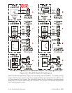
2-40 / Installation & Operation CI-ControlWave EFM
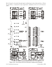
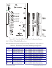
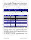
Table 2-13 - 21V Power Supply Board Terminal Designations
21VPS
TB#
21VPS
TB NAME
CONNECTION
to PDB.
CONNECTION
to XMTR.
TB1-1 +12VIN TB3-1 N/A
TB1-2 12VGND TB3-2 N/A
TB1-3 CHASSISGND N/A N/A
TB2-1 +21V N/A XMTR1+
TB2-2 21VGND N/A XMTR1-
TB2-3 +21V N/A XMTR2+
TB2-4 21VGND N/A XMTR2-
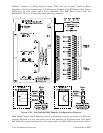
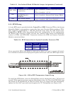
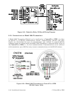
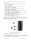
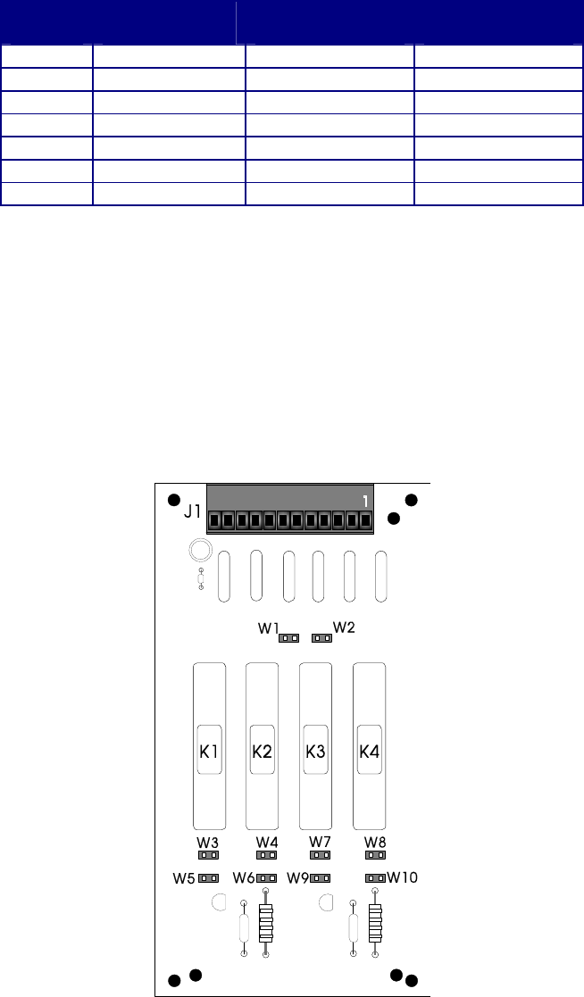
2.3.7 Digital to Relay I/O Board Option
Digital to Relay I/O Boards except up to two discrete input signals from an open drain
MOSFET device and convert them to Form C relay output signals using Solid State Relay
(SSR) logic. The minimum current load will be 100mA. Figure 2-27 provides a component
view of the Digital to Relay I/O Board.
Each ControlWave EFM Discrete Output is converted to a Form C relay output signal
which can be configured for opposite or identical state conditions, i.e., both Normally Open
(NO) or Normally Closed (NC) or one Normally open with the other Normally Closed.
Figure 2-27 - Digital to Relay I/O Board
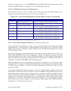
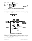
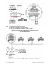
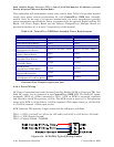
2.3.7.1 Digital to Relay I/O Board Jumper Settings
The Digital To Relay I/O Board contains ten (10) Jumpers which allow the user to configure
contacts for Normally Open/Normally Closed states. Contacts associated with each of the
Form C Relays may be configured for identical or opposite states. Note: Jumper Pairs
W3/W5, W4/W6, W7/W9 and W8/W10 must be set in opposite states.