


CI-ControlWave EFM Contents / 0 - 1
CI-ControlWave EFM
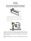
ControlWave EFM
Electronic Flow Meter
TABLE OF CONTENTS
SECTION TITLE PAGE #
Section 1 - ControlWave EFM INTRODUCTION
1.1 GENERAL DESCRIPTION ...........................................................................................1-1
1.2 ControlWave PROGRAMMING ENVIRONMENT ....................................................1-5
1.3 PHYSICAL DESCRIPTION...........................................................................................1-7
1.3.1 Enclosure.........................................................................................................................1-8
1.3.2 CPU Module....................................................................................................................1-8
1.3.2.1 CPU Module Connectors ..............................................................................................1-10
1.3.2.2 CPU Memory.................................................................................................................1-10
1.3.2.3 CPU Module Configuration Jumpers ..........................................................................1-11
1.3.2.4 CPU Module Configuration Switches..........................................................................1-11
1.3.2.5 CPU Module LEDs .......................................................................................................1-12
1.3.3 System Controller Module (SCM)................................................................................1-12
1.3.3.1 SCM Mode Switch.........................................................................................................1-13
1.3.3.2 SCM Board Fuse...........................................................................................................1-13
1.3.3.3 SCM Board Connectors ................................................................................................1-14
1.3.3.4 SCM Jumpers ...............................................................................................................1-14
1.3.3.5 SCM LEDs.....................................................................................................................1-14
1.3.4 ControlWave EFM Backplanes..................................................................................1-14
1.3.5 ControlWave EFM Base Assembly Chassis..............................................................1-15
1.3.6 ControlWave EFM I/O Modules ................................................................................1-16
1.3.6.1 Non-isolated Analog I/O & Analog Input Modules .....................................................1-17
1.3.6.2 Non-isolated Digital Input/Output Module.................................................................1-17
1.3.6.3 Non-isolated High Speed Counter Input Module........................................................1-17
1.3.6.4 Non-isolated Mixed Input/Output Module..................................................................1-17
1.3.7 ControlWave EFM Expansion Communications Modules.......................................1-17
1.3.8 Internal Mounting Brackets ........................................................................................1-18
1.3.9 Multivariable Transducer ............................................................................................1-19
1.3.10 Power Distribution Board ............................................................................................1-19
1.3.11 Digital to Relay I/O Option ..........................................................................................1-19
1.3.12 21V Power Supply Option............................................................................................1-20
1.3.13 Power System................................................................................................................1-20
1.3.14 RTD Probe.....................................................................................................................1-21
1.3.15 External Radio/Modem.................................................................................................1-21
1.4 FIELD WIRING............................................................................................................1-21
1.5 FUNCTIONS.................................................................................................................1-21
1.5.1 Data Acquisition ...........................................................................................................1-22
1.5.2 Flow and Volume Calculations ....................................................................................1-22
1.5.2.1 Flow Rate and Flow Time Calculations (AGA3) .........................................................1-23
1.5.2.2 Flow Rate Calculations and Flow Time Accumulations (AGA7) ...............................1-23
1.5.2.3 Extension Calculation and Analog Averaging ............................................................1-23
1.5.2.3.1 Energy Calculation.......................................................................................................1-23
1.5.2.3.2 Volume and Energy Integration ..................................................................................1-23
1.5.2.4 Downstream Pressure Tap...........................................................................................1-23
1.5.3 Archives.........................................................................................................................1-24
1.5.3.1 Hourly Historical Data Log..........................................................................................1-24