


S1400CW Page 5-4 Section 5 - Wiring Techniques
Remember loose connections, bad connections, intermittent connections, corroded connec-
tions, etc., are hard to find, waste time, create system problems and confusion in addition to
being costly.
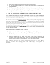
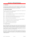
5.2.7 High Power Conductors and Signal Wiring
When routing wires, keep high power conductors away from signal conductors. Space wires
appropriately to vent high voltage inductance. Refer to the National Electrical Code
Handbook for regulatory and technical requirements.
5.2.8 Use of Proper Wire Size
ControlWaves utilize compression-type terminals that accommodate up to #14 AWG gauge
wire. A connection is made by inserting the bared end (1/4 inch max.) into the clamp
beneath the screw and securing the screw.
Allow some slack in the wires when making terminal connections. Slack makes the
connections more manageable and minimizes mechanical strain on the PCB connectors.
Provide external strain relief (utilizing Tie Wrap, etc.) to prevent the loose of slack at the
ControlWave.
Be careful to use wire that is appropriately sized for the load. Refer to equipment
manufacturer’s Specs. and the National Electrical Code Handbook for information on wire
size and wire resistance. After installing the field wiring, test each load to determine if the
correct voltage or current is present at the load. If you know the resistance of the field wires
(Circular Mills x Length) you should be able to calculate the load voltage. Conversely, if you
know the minimum load voltage and current, you should be able to derive the maximum
voltage loss that is allowable due to line resistance and then the correct wire size.
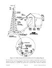
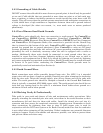
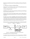
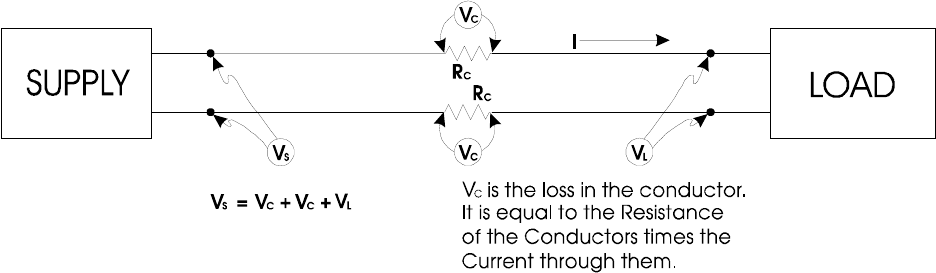
Referring to Figure 5-2, a relay that is picked by 100 mA, with a loop supply voltage of 24V
and a total line resistance of 20 ohms, the load voltage (voltage across the relay) should be:
V
L
= V
S
- (V
C
+ V
C
) where V
C
+ V
C
= (R
C
+ R
C
) I
22 = 24 - 2 where 2V = (20 Ω) x 0.1 A
Figure 5-2 - Calculating Load Voltage due to Line Resistance
5.2.9 Lightning Arresters & Surge Protectors
Use lightning arresters in association with any radio or modem equipped unit. BBI 9600
bps modems are equipped with surge protection circuitry. Lightning arresters or Antenna