


CI-ControlWave EFM Appendix C - Hardware Installation Guide / C-13
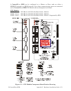
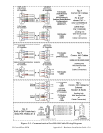
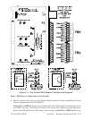
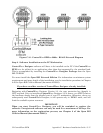
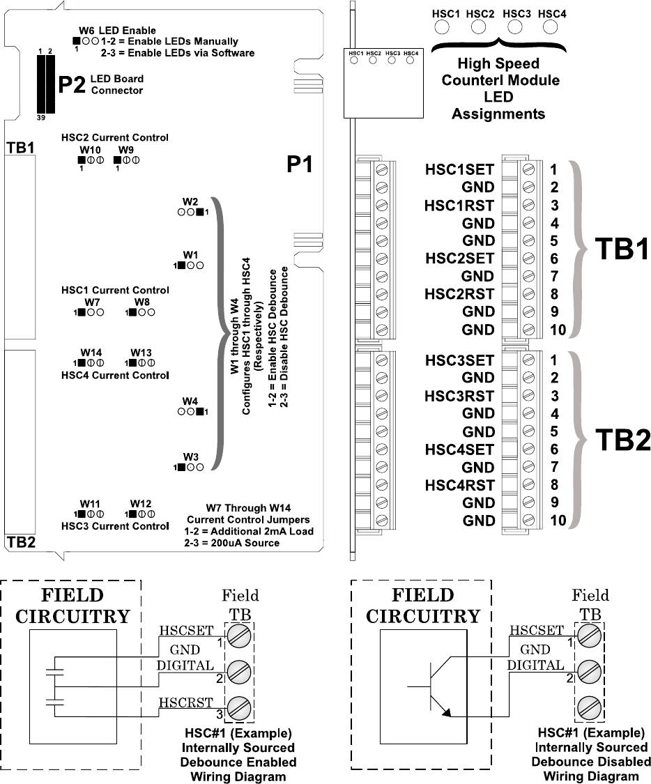
Figure C-8 - Non Isolated HSC Module Configuration Diagram
Step 1. Hardware Configuration (Continued)
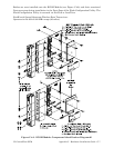
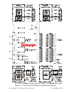
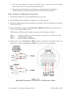
6. Install a ground wire between the Chassis Ground Lug and a known good Earth Ground
(also see Supplement Guide S1400CW).
ControlWave EFM Housings are provided with a Ground Lug that accommodates up to
a #4 AWG wire size. A ground wire must be run between the Chassis Ground Lug and a
known good Earth Ground. The cases of the various ControlWave EFM Modules are