


CI-ControlWave EFM Contents / 0 - 3
CI-ControlWave EFM
ControlWave EFM
Electronic Flow Meter
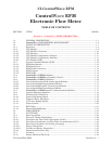
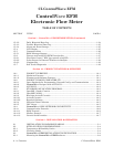
TABLE OF CONTENTS
SECTION TITLE PAGE #
Section 2 - INSTALLATION & OPERATION (Continued)
2.3.1.1 Connection to the Multivariable Transducer (MVT) ..................................................2-10
2.3.1.2 Process Pipeline Connection (Meter Runs without Cathodic Protection) .................2-11
2.3.1.3 Process Pipeline Connection (Meter Runs with Cathodic Protection).......................2-11
2.3.2 System Controller Module (SCM) Configuration........................................................2-13
2.3.3 CPU Module & ECOM Module Configuration............................................................2-14
2.3.3.1 CPU Module Switch Configuration .............................................................................2-14
2.3.3.2 Communication Ports...................................................................................................2-16
2.3.3.3 RS-232 & RS-485 Interfaces ........................................................................................2-17
2.3.3.4 Piggy-back Spread Spectrum Modem (Radio) Port ....................................................2-22
2.3.3.5 Piggy-back 56K PSTN Modem Port.............................................................................2-23
2.3.3.6 Radio Ready and External (Case Mounted) Modem or Radio....................................2-27
2.3.4 I/O Module Installation & Wiring................................................................................2-27
2.3.4.1 Installation of I/O Modules ..........................................................................................2-27
2.3.4.2 I/O Wire Connections....................................................................................................2-30
2.3.4.3 Shielding and Grounding .............................................................................................2-30
2.3.4.4 Non-isolated Digital Input/Output Module.................................................................2-30
2.3.4.4.1 Digital Input/Output Configurations ..........................................................................2-30
2.3.4.5 Non-isolated Analog Input/Output & Analog Input Modules....................................2-31
2.3.4.5.1 Analog Input/Output Configurations ..........................................................................2-33
2.3.4.6 Non-isolated High Speed Counter Input Module........................................................2-33
2.3.4.6.1 High Speed Counter Configurations............................................................................2-35
2.3.4.7 Non-isolated Mixed I/O Module ...................................................................................2-35
2.3.4.7.1 Mixed I/O Module Configuration.................................................................................2-37
2.3.5 RTD Wiring...................................................................................................................2-38
2.3.6 21V Power Supply Option ............................................................................................2-39
2.3.7 Digital to Relay I/O Board Option ...............................................................................2-40
2.3.7.1 Digital to Relay I/O Board Jumper Settings...............................................................2-40
2.3.8 Connection to a Model 3808 Transmitter....................................................................2-42
2.3.9 Power Wiring & Distribution.......................................................................................2-44
2.3.9.1 Bulk Power Supply Current Requirements ................................................................2-45
2.3.9.2 Power Wiring ................................................................................................................2-46
2.3.9.3 Mounting an Optional Solar Panel..............................................................................2-47
2.3.9.3.1 Swivel (Directional Facing)..........................................................................................2-47
2.3.9.3.2 Tilt Angle.......................................................................................................................2-48
2.3.9.4 Installing the Rechargeable Battery and Solar Panel Harness.................................2-48
2.3.9.5 ControlWave EFM System Grounding......................................................................2-49
2.3.10 Operation of the Lithium Backup Coin-cell Battery ..................................................2-49
2.3.11 Installation of a Bezel Assembly..................................................................................2-50
2.4 OPERATIONAL DETAILS..........................................................................................2-51
2.4.1 Downloading the Application Load..............................................................................2-51
2.4.2 Upgrading ControlWave EFM Firmware .................................................................2-51
2.4.2.1 Using LocalView to Upgrade ControlWave EFM Firmware ...................................2-52
2.4.2.2 Using Hyperterminal to Upgrade ControlWave EFM Firmware............................2-55