


CI-ControlWave EFM Specifications / 4-3
Shutdown: +6V System:
Max. ON Switchpoint = 4.90V
Min. OFF Switchpoint = 4.33V
+12V System:
Max. ON Switchpoint = 10.3V
Min. OFF Switchpoint = 9.28V
4.3.2 Power Supply Sequencer Specs.
Signals Monitored: Input Power
Sequencer Switchpoints: +3.3V Max. ON Switchpoint = +3.15V
+3.3V Min. OFF Switchpoint = +3.00V
+1.8V Max. ON Switchpoint = +1.72V
+1.8V Min. OFF Switchpoint = +1.64V
Sequencer Output Signals: PFDLYCLK Timing on power down 2msec after POWER-
FAIL
VIN100M timing on power Up 1200msec delay for Good
Power
POWERGOOD incoming power, 3.3V & 1.8V in Spec.
4.3.3 Power Supply External Power Monitor Specs.
Input Signal: Input power after fuse, before Diode
Input Range: 0Vdc to 16Vdc
Resolution: 17 Bit
Accuracy: Uncalibrated: ±3% @ +25°C (+77°F)
Uncalibrated: ±4% over -40 to +85°C (-6.2 to +185°F)
Calibrated: ±0.1% @ +25°C (+77°F)
Calibrated: ±1.1% over -40 to +85°C (-6.2 to +185°F)
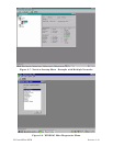
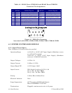
4.3.4 System Controller Module Connectors (see Figure 4-2, Tables 4-3 & 4-4)
Table 4-3 - System Controller Module Connector Summary
Ref. # Pins Function
P1 44-pin Backplane Connector
P2 8-pin MVT Interface Connector
TB1 3-pin Input Power Term. Block (see Table 4-4)
TB2 3-pin RTD Intf. Connector (see Section 2.3.5)
J2 8-pin Display/Keypad Intf. Connector (RJ-45)
Table 4-4 - System Controller Module Input Power Terminal Block Assignments
TERM. # NAME FUNCTION
TB1-1 +VIN +6Vdc or +12Vdc (nominal) Input
TB1-2 -VIN Supply Common
TB1-3 CHASSIS
Chassis Ground