


CI-ControlWave EFM Introduction / 1-9
Backup Battery Jumper JP1 (on the Battery Backup Board) from position 1 to 2 and then
storing it on either pin. If the Real-time clock looses its battery backup a ControlWave
Designer system variable bit (_QUEST_DATE) is set. This bit can be used to post a
message or alarm to the PC (see the ‘Systems Variables’ section of the ControlWave
Designer Programmer’s Handbook D5125).
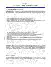
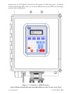
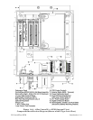
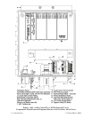
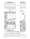
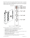
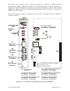
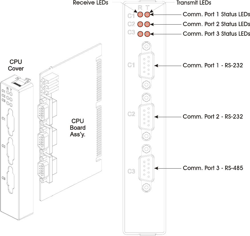
Figure 1-5 – ControlWave EFM CPU Module
Basic CPU components and features are summarized as follows:
• LH7A400 System-on-Chip 32-bit ARM9TDMI RISC Core microprocessor
• 512KB FLASH Boot/Downloader, 29LV040B, 90 nS, 8-bit access
• 2MB SRAM, 3.3V, 512K x 32, with Battery Back-up
• 8MB simultaneous read/write FLASH, TSOP sites
• Two 9 wire PC2 compatible (RS-232) serial communications ports with modem control
pins and one 5 wire RS-485 Comm. port
• I/O Bus Interface capable of driving up to 14 I/O Modules
• Spread Spectrum clock for lower EMI
• Two Status LEDs per Comm. Port
• 8-Position general-purpose switch bank plus a 4-Position recovery switch bank
• Coin cell socket accepts a 3.0V, 300mA-hr lithium battery