


2-16 / Installation & Operation CI-ControlWave EFM
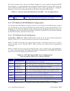
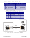
Table 2-3 - CPU Bd. Switch SW1 - Force Recovery Mode/Battery Enable
Switch Function Setting - (OFF = Factory Default)
SW1-3 Force Recovery Mode
ON = Force recovery mode (via CW Console)
OFF = Recovery mode disabled
Note: SW1-1, SW1-2 and SW1-4 are not used.
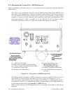
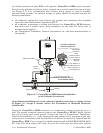
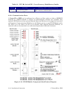
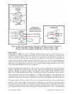
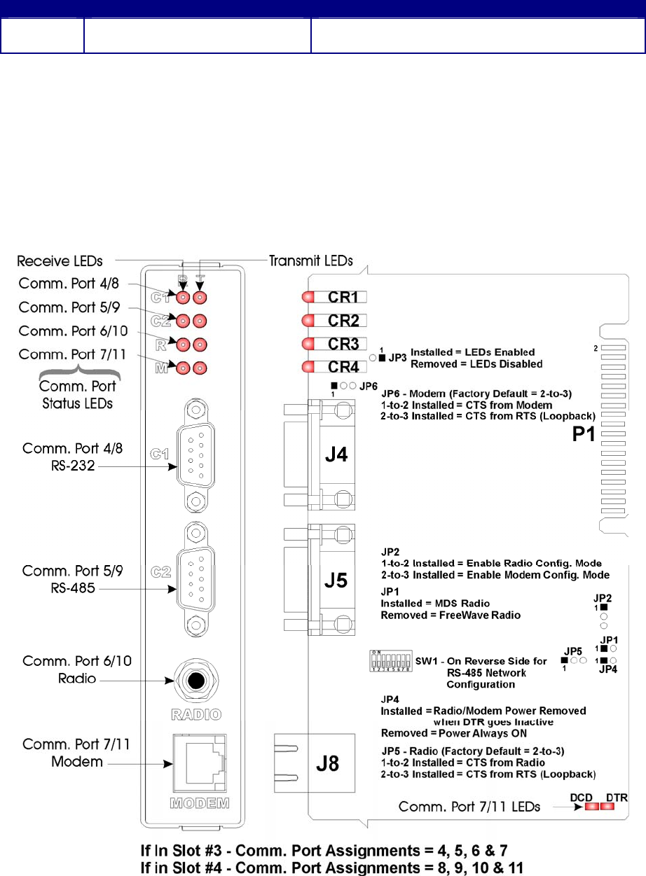
2.3.3.2 Communication Ports
A ControlWave EFM can be configured as a Master or Slave node on either a MODBUS
network or a BSAP network. A variety of communication schemes are available. One
optional 56K Modem and one optional Spread Spectrum Modem can be piggy-back mounted
on Expansion Communications Modules (or the Modem can be on one ECOM Module while
the radio is on the other). In lieu of an internal radio (Spread Spectrum Modem), an
external radio can be mounted on a radio mounting bracket within the enclosure.
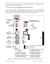
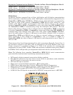
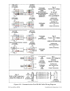
Figure 2-10 - ECOM Module Component Identification Diagram