


CI-CW MICRO/CW EFM Appendix E - Display/Keypad / E-1
Appendix E
DISPLAY/KEYPAD ASSEMBLY GUIDE
E1.1 OVERVIEW
Bristol, Inc. Display/Keypad assemblies provide a built-in, local, user interface for the
ControlWave MICRO or the ControlWave EFM. These assemblies allow an operator or
engineer to view and modify variable values and associated status information, via an
ACCOL3 Function Block. Variables can include inputs, process variables, calculated
variables, constants, setpoints, tuning parameters and outputs used in a measurement or
control application. Status bits include alarm state, alarm acknowledge, control, manual,
and questionable data.
Setting up the Display/Keypad is a simple matter of configuring a Display Function Block
in the ControlWave Designer project.
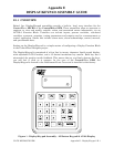
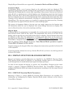
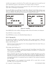
The Display/Keypad is comprised of a four line by twenty character liquid crystal display,
with adjustable LCD Contrast, and a 25 button membrane key matrix. Each key has a
microswitch for positive tactile feedback. This means that as you firmly depress the keys,
you will feel it click as it engages. In the case of the ControlWave EFM, the
Display/Keypad is located in the Instrument Front Cover and is installed at the factory.
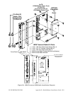
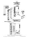
Figure 1 - Display/Keypad Assembly – 25 Button Keypad & 4 X 20 Display