


D-2 / Appendix D - Radio/Modem Installation Guide CI-CW MICRO/CW EFM
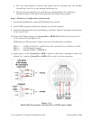
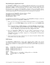
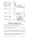
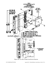
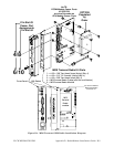
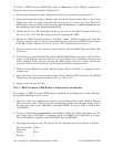
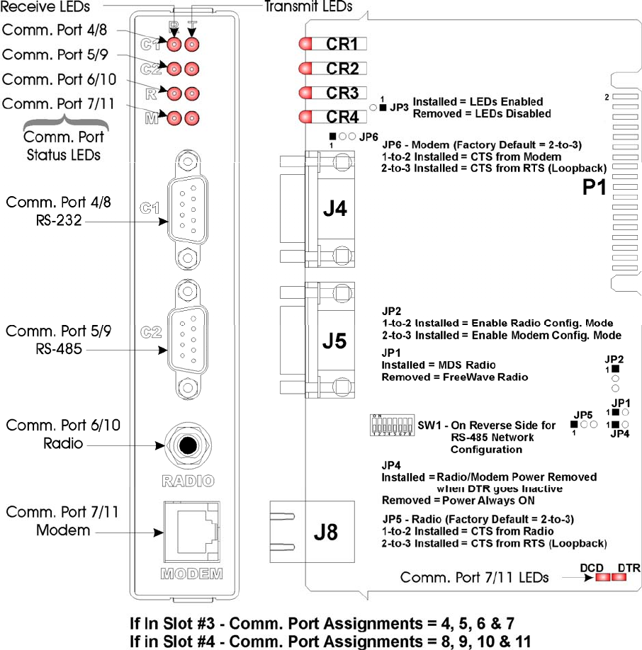
Figure D1 – Expansion Comm. Module Component Identification Diagram
D1.1.2 Configuring the FreeWave Radio (FGR09CSU)
To configure a Model FGR09SCU Radio (installed on an Expansion Communication
Module), perform the following eight (8) steps:
1. If required, remove the Exp. Comm. Module from the unit in question (see Figure. D1).
2. Place the radio into configuration ode by setting Expansion Comm. Module Jumper JP2
onto pins 1 and 2. This will enable configuration of the radio through Comm. Port 4 for
radio on Comm. Port 6 (ECOM1) or through COMM. Port 8 for radio on Comm. Port 10
(ECOM2).
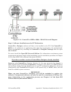
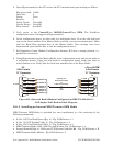
3. Connect a Full Duplex ControlWave Null Modem Cable (see Figure D3) between a PC
and Comm. Port 4 (ECOM1) to configure radio on COMM. Port 6 (ECOM1) or Comm.
Port 8 (ECOM2) to configure radio on COMM. Port 10 (ECOM2).