


2-22 / Installation & Operation CI-ControlWave EFM
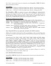
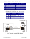
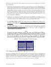
by configuring CPU Bd. Switch SW3 and/or ECOM Switch SW1 (COM6/COM9) so that the
100-Ohm termination resistors and biasing networks are installed at the end nodes and are
removed at all other nodes on the network (see Table 2-6).
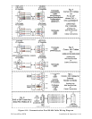
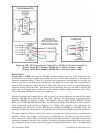
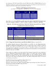
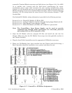
Table 2-5 - RS-485 Network Connections
(see Table 2-4A ControlWave EFM RS-485 Port Pin # Assignments)
From
Master
To 1st
Slave
To nth
Slave
TXD+ RXD+ RXD+
TXD- RXD- RXD-
RXD+ TXD+ TXD+
RXD- TXD- TXD-
GND/ISOGND*
GND/ISOGND* GND/ISOGND*
* ISOGND with Isolated RS-485 Ports Only!
Note: Pins 1, 2, 3, 4 & 9 of BBI Series 3305, 3310, 3330, 3335 & 3340 RTU/DPC RS-485 Comm.
Ports are assigned as follows: 1 = TXD+, 2 = TXD-, 3 = RXD+, 4 = RXD- & 9 = ISOGND.
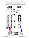
Table 2-6 - CPU Bd. Switch SW3 for COM3 & ECOM Bd. Switch SW1 for COM5/9
Loopback & Termination Control
SWITCH
#
RS-485 Function
Switch ON
Setting
1 TX+ to RX+ Loopback ON - for Half Duplex Network or Diagnostics
2 TX- to RX- Loopback ON - for Half Duplex Network or Diagnostics
3 100 Ohm RX+ Termination ON - End Nodes Only
4 100 Ohm RX- Termination ON - End Nodes Only
5 N/A N/A
6
(see note 2)
Slew Rate
ISO485 ONLY
ON - Slow Rate Enabled
OFF - Fast Rate Enabled
7 RX+ Bias (End Node) ON - End Nodes Only
8 RX- Bias (End Node) ON - End Nodes Only
Note 1: Closed = Switch set ON Note 2: Switch SW3 (COM3) = N/A
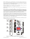
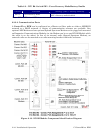
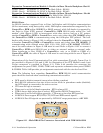
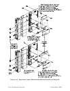
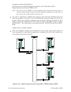
2.3.3.4 Piggy-back Spread Spectrum Modem (Radio) Port (see Appendix D)
An optional Spread Spectrum Modem (Radio) is available on each Expansion Com-
munications Module (mounted piggy-back) and is assigned port status as follows: COM6 for
ECOM1 and COM10 for ECOM2. There are two unique radios offered. These radios will
only communicate with their own brand of radio, i.e., FreeWave radios are not compatible
with MDS radios. DTE/DCE serial data can be clocked into (transmit) or out of (receive) the
radio at a rate up to 115.2kHz.
These radios are supplied in kit form with all the hardware required for user installation
onto an Expansion Communications Module. Figure 2-14 shows both versions of radios
mounted on the Expansion Comm. Module. Radios are user installed onto the ECOM
Module (see Figure 2-14) and their associated Ports are setup during installation in the
Ports Page of the Flash Configuration Utility. The Flash Configuration Utility is accessed
via NetView or LocalView.
FreeWave® Spread Spectrum Wireless Data Transceiver:
Operates in the 902 to 928 MHz range (20 miles).
Microwave Data System Inc. MDS TransNET OEM™ Spread Spectrum Data Transceiver:
Operates in the 902 to 928 MHz range (20 miles).