


Section 3 - Grounding & Isolation Page 3-5 S1400CW
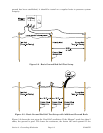
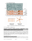
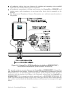
Figure 3-5 - Poor Soil Ground Bed Construction Diagram
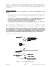
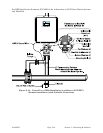
3.3.2 Ground Wire Considerations
ControlWave, ControlWave MICRO, ControlWave EFM/GFC/XFC, Control-
WaveRED, ControlWave REDIO & ControlWave I/O Expansion Rack
ControlWave Chassis are provided with a Ground Lug that accommodates up to a #4 AWG
wire size. A ground wire must be run between the Chassis Ground Lug and a known good
Earth Ground. The cases of the various ControlWave Modules are connected to Chassis
Ground when they have been installed and secured via their two Captured Panel
Fasteners. As an extra added precaution, it is recommended that a #14 AWG wire be run
from PSSM Power Connector TB2-5 (Chassis Ground) (PSSM Connector TB1-3 for
ControlWave MICRO unit) (SCM Connector TB1-3 for ControlWave EFM) to the same
known good Earth Ground.
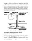
ControlWaveLP Process Automation Controller
A #14 AWG ground wire must be run from the ControlWaveLP’s PSSB Terminal TB2-3
(Chassis Ground) to a known good Earth Ground. In lieu of a direct connection to Earth