


CI-ControlWave EFM Installation & Operation / 2-41
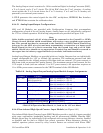
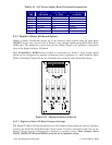
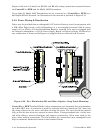
The commons associated with each form C Relay (R0COM and R1COM) have the option of
being tied to the ControlWave EFM Power Ground or to a floating Ground. Jumper W1 is
associated with Outputs R0A and R0B and W2 is associated with outputs R1A and R1B.
When Jumper W1 is installed the common (C) associated with Outputs R0A and R0B is tied
to ControlWave EFM Power ground; when Jumper W1 is not installed, the common will
be floating. When Jumper W2 is installed the common (C) associated with Outputs R1A and
R1B is tied ControlWave EFM Power ground; when Jumper W2 is not installed, the
common will be floating.
Table 2-14 - Jumper Settings versus Form C Relay Output States
JUMPERS
W3/W5
R0A
STATE
JUMPERS
W4/46
R0B
STATE
JUMPERS
W7/W9
R1A
STATE
JUMPERS
W7/W9
R1B
STATE
IN/OUT NO IN/OUT NO IN/OUT NO IN/OUT NO
OUT/IN NC OUT/IN NC OUT/IN NC OUT/IN NC
Table 2-13 provides the relationship between Jumper settings and Form C Relay Outputs.
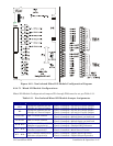
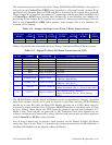
Table 2-15 - Digital To Relay I/O Board Connections to J1/P1
J1 Pin Signal Function Wiring Connections
1 R1B Relay 1 Output B To Field
2 R1A Relay 1 Output A To Field
3 R1COM Relay 1 Common To Field (See W2)
4 CHASSIS GND Chassis Ground CWMICRO Chassis Gnd. Lug
5 R0COM Relay 0 Common To Field (See W1 - Section 1.1.1)
6 ROB Relay 0 Output B To Field
7 ROA Relay 0 Output A To Field
8 - - -
9 POWER GND Power Ground
Pwr. Dist. Bd.
TB4 Pin 2 (Black Wire)
10 POWER - DC Power - 6/12 Vdc
Pwr. Dist. Bd.
TB4 Pin 1 (Red Wire)
11 DOUT0 Discrete Output 0
DI/O Module TB2-5 - TB2-8 or
Mixed I/O Module TB1-1 - TB1-6 (Yellow Wire)
12 DOUT1 Discrete Output 1
DI/O Module TB2-6 - TB2-8 or
Mixed I/O Module TB1-2 - TB1-6 (Orange
Wire)
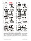
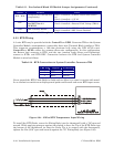
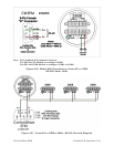
The DI/DO Module and the Mixed I/O Module provide independently firmware controlled
open drain outputs, which can be used for control or signaling functions (DI/DO Modules
provide up to four DO while the Mixed I/O Module provides up to 6 DO). Each output is
wired to the source terminal of an N Channel MOSFET capable of switching up to 16 Volts
at up to 100mA. When closed, the FET shorts the output to ground with resistance of .5
Ohms or less. These outputs are protected by 16V Transorbs. Since these outputs are not
isolated, caution must be exercised to ensure that the load current does not affect operation
of the ControlWave EFM or related devices.
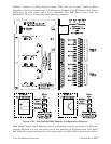
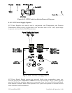
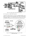
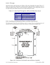
Two of these outputs may be wired to field circuitry via the Digital to Relay I/O Board
option (see Figure 2-28). Table 2-15 provides the wiring connections for the DI/O Module or
the Mixed I/O Module and the Digital to Relay I/O Board.