


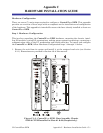

ControlWave EFM
Special Instructions for Class I, Division 2 Hazardous Locations
10/06/2006 Appendix A, Document CI-ControlWave EFM Page 2 of 2
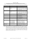
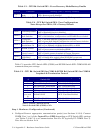
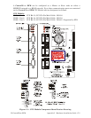
Table A1 -Module/Board Connector Customer Wiring Connectors (Continued)
Module/Item Connector Wiring Notes
SCM Module TB1 - Input Power Typically Factory Wired - *
SCM Module TB2 - RTD Interface
Field Wired - Refer to ¶ 9 of this document.
Exp. Comm Module 1 J4 - COM4, 9-pin Male D-sub
RS-232
J5 - COM5, 9-pin Male D-sub
RS-485
Remote Comm. Port: For Radio or external
Network Comm. Refer to Model Spec. and ¶ 10
of this document. When used for Network
Comm., use Div. 2 wiring methods. If COM4 is
used in conjunction with a radio/modem refer
to 11 of this document.
Exp. Comm Module 1 J8 - COM7, RJ11 Female Modular connection to Phone Co. equipment.
Exp. Comm Module 2 J4 - COM8, 9-pin Male D-sub
RS-232
J5 - COM9, 9-pin Male D-sub
RS-485
Remote Comm. Port: For Radio or external
Network Comm. Refer to Model Spec. and ¶ 10
of this document. When used for Network
Comm., use Div. 2 wiring methods. If COM8 is
used in conjunction with a radio/modem refer
to 11 of this Document.
Exp. Comm Module 2 J8 - COM11, RJ11 Female Modular connection to Phone Co. equipment.
Refer to ¶ 6, 7, 8 & 11of this document.
Analog I/O Module TB1/TB2 - 10-pin Term. Blocks Field I/O wiring connectors are unrated; use
Div. 2 wiring methods. *
Digital I/O Module TB1/TB2 - 10-pin Term. Blocks Field I/O wiring connectors are unrated; use
Div. 2 wiring methods. *
HSC Input Module TB1/TB2 - 10-pin Term. Blocks Field Input wiring connectors are unrated;
use Div. 2 wiring methods. *
Mixed I/O Module TB1/TB2 - 10-pin Term. Blocks Field I/O wiring connectors are unrated; use
Div. 2 wiring methods. *
Digital To Relay I/O Bd. J1 10-pin In-line Connector Field I/O wiring connector is unrated, use Div.
2 wiring methods. Refer to ¶ 12 of this
document. *
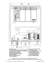
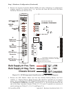
Power Distribution Bd.
(see ¶ 5 - this document)
TB1 - 3-pin Term Block
TB2 - 2-pin Term Block
TB3 - 2-pin Term Block
TB4 - 2-pin Term Block
TB5 - 2-pin Term Block
TB6 - 2-pin Term Block
Primary Power Input - User wired *
Main Power Out 1 - Factory wired *
Main Power Out 2 - Factory wired *
Fused Power Out 1 - Factory wired *
Fused Power Out 2 - Factory wired *
Fused Power Out 3 - Factory wired *
21V Power Supply Bd.
(see ¶ 5 & 13 of
this document)
TB1 - 3-pin Term Block
TB2 - 4-pin Term Block
12V Power Input - Factory wired *
21V Transmitter Power -Field Wired
TB2 is unrated, use Div. 2 wiring methods.
Enclosure Bottom Local Port Circular Connector
Local Comm. Port - Factory Wired. Refer to 
3 of this document. *
Note: * = These wires should only be installed/removed when the item (PCB) in question is
installed/removed or when checking wiring continuity. The area must be known to be
nonhazardous before servicing/replacing the unit and before installing or removing PCBs,
Connectors or individual I/O or Power wires. Refer to
6, 7 & 8 of this document. All input
power and I/O wiring must be performed in accordance with Class I, Division 2 wiring
methods as defined in Article 501-4 (b) of the National Electrical Code, NFPA 70, for
installations within the United States, or as specified in Section 18-152 of the Canadian
Electrical Code for installation in Canada.