


2-18 / Installation & Operation CI-ControlWave EFM
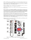
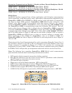
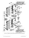
Expansion Communications Module 1: Resides in Base Chassis Backplane Slot #3
COM4 - Port 1: ECOM Bd. J1, PC/AT 9-Pin Male D-Sub - RS-232
COM5 - Port 2: ECOM Bd. J2, PC/AT 9-Pin Male D-Sub - RS-485
Expansion Communications Module 2:
Resides in Base Chassis Backplane Slot #4
COM8 - Port 1: ECOM Bd. J1, PC/AT 9-Pin Male D-Sub - RS-232
COM9 - Port 2: ECOM Bd. J2, PC/AT 9-Pin Male D-Sub - RS-485
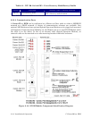
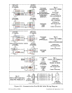
RS-232 Ports
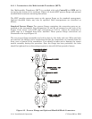
An RS-232 interface supports Point to Point, half-duplex and full-duplex communications
(20 feet maximum, using data quality cable). Half-duplex communications supported by the
ControlWave EFM utilize MODBUS or BSAP protocol, while full-duplex is supported by
the Point to Point (PPP) protocol. ControlWave EFM RS-232 ports utilize the “null
modem” cable (Figure 2-12A) to interconnect with other devices such as a PC, printer,
another ControlWave EFM or ControlWave series unit (other than CW_10/30/35) when
the ControlWave EFM is communicating using the full-duplex PPP protocol. The half-
duplex cable shown in Figure 2-12A is utilized when the ControlWave EFM is connected
to another ControlWave EFM or ControlWave series unit (other than CW_10/30/35). If
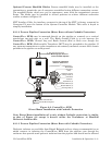
communicating with a Bristol series 3305, 3310, 3330, 3335 or CW_10/30/35 RTU/DPC,
one of the cables shown in Figure 2-12B must be used. Refer to Figure 2-12C to connect a
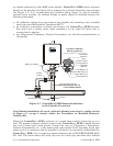
ControlWave EFM serial RS-232 port to either an external modem or external radio.
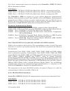
When interfacing to Port COM3 of a ControlWave unit, or to COM5 or COM6 of a
ControlWaveEXP, the cable of Figure 2-12D must be used along with the one of Figure 2-
12A or 2-12B.
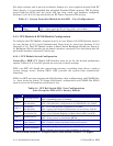
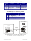
Illustrations of the Local Communication Port cable connections (Typically Comm. Port 1)
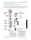
are provided in Figures 2-13A and 2-13B. An illustration of the CPU Module’s male 9-pin
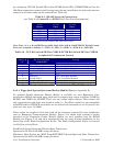
D-type connectors is provided in Figure 2-11. Table 2-4A provides the connector pin
assignments for ports COM1, COM2, COM3 and expansion communications ports COM4/5
& COM8/9. Table 2-4B provides pin assignments associated with the circular Local Port.
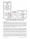
Note: The following facts regarding ControlWave EFM RS-232 serial communication
ports should be observed when constructing communications cables:
• DCD must be high to transmit (except when dialing a modem)
• Each RS-232 transceiver has one active receiver while in powerdown mode (disabled);
the DCD signal is connected to the active receiver.
• CTS must be high to transmit.
• When port is set for full-duplex operation - RTS is always ON.
• DTR is always high (when port is active); DTR enables RS-232 Transceivers.
• When port is set for half-duplex operation - CTS must go low after RTS goes low.
• All RS-232 Ports support RTS, DTR, CTS, DCD and DSR control signals.
• All RS-232 Port I/O signals are protected by LCDA12C surge protectors to ±4KV ESD.
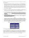
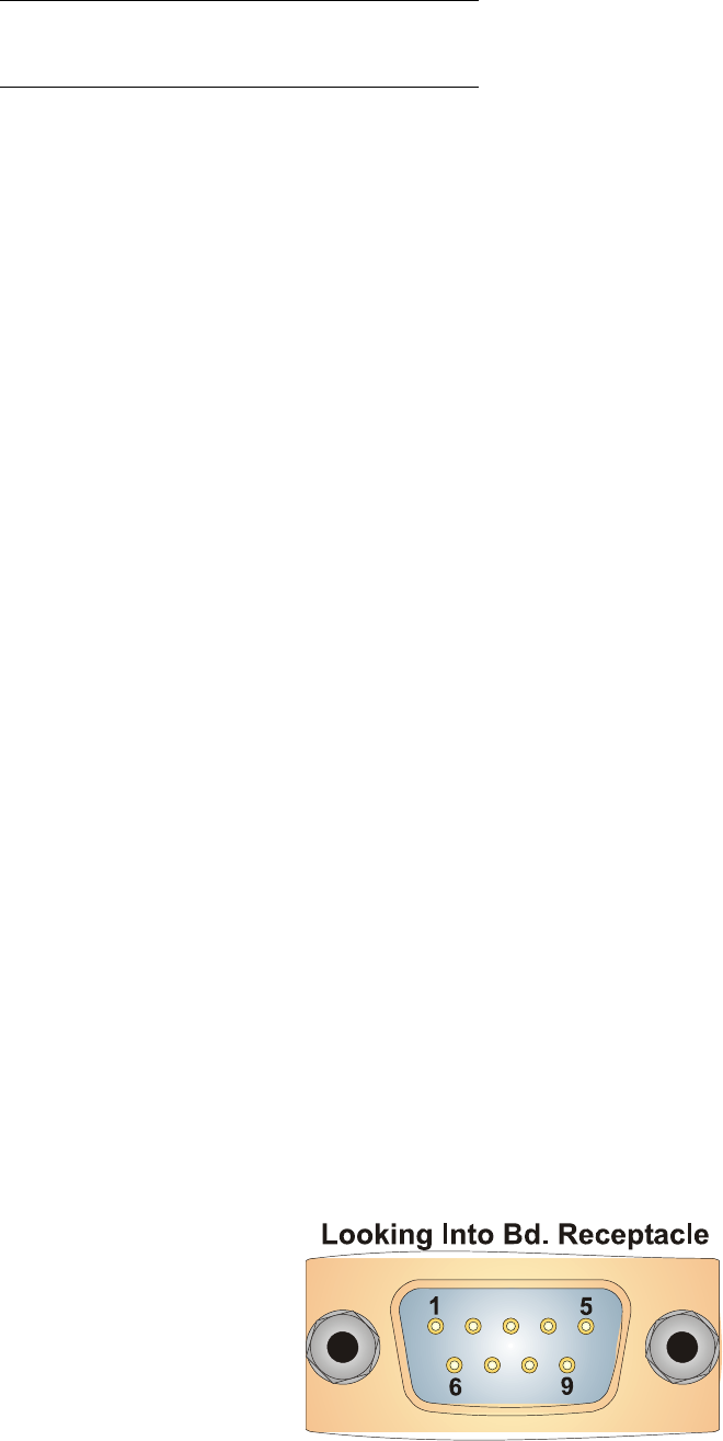
Figure 2-11 - Male DB9 9-Pin Connector Associated with COM1/2/3/4/5/8/9