


F-30 / Appendix F CI-ControlWave EFM
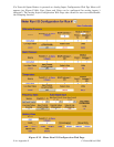
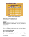
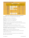
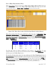
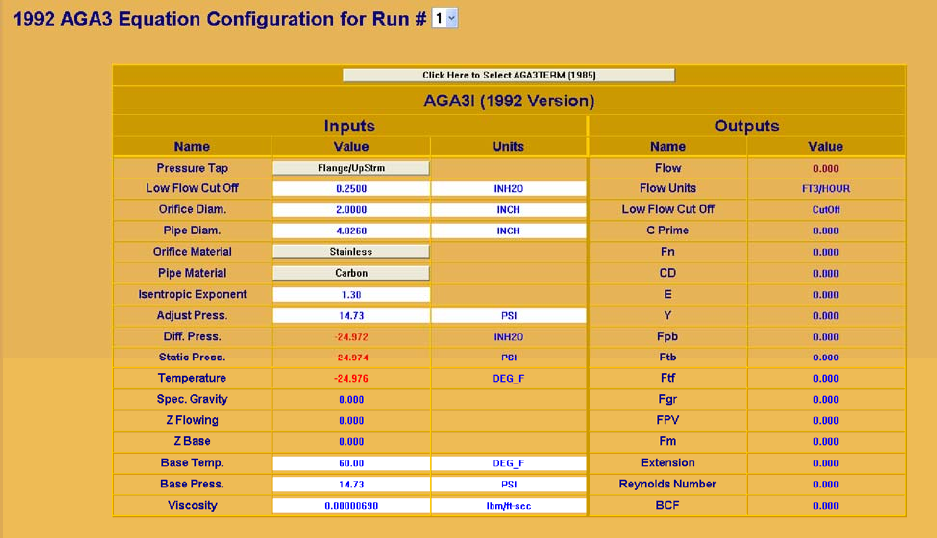
Figure F-18B - (1992 AGA3) Orifice Flow Equation Setup Web Page
Adjust Press. - Users enter Average Barometric Pressure here (psia).
Diff. Press. - Actual value in use is displayed here.
Static Pressure - Actual value in use is displayed here.
Temperature - Actual value in use is displayed here.
Spec. Gravity - Specific Gravity of the gas being measured is displayed here.
Z Flowing - Flowing compressibility Factor, Zf, generated from the AGA8 calculation
referenced to upstream conditions.
Z Base - Base compressibility Factor from the AGA8 Gross calculation.
Base Temperature - Required and Contract Base Temperate is entered here (Deg. F).
Base Pressure - Required or Contract Base Pressure is entered here (psia). The following
outputs from the AGA3 calculation are displayed:
MSCF/H - Flow rate in thousands of standard cubic feet per hour
Low Flow Cut Off - Cutoff (if the DP drops below the low flow cut off value) or OK
C Prime - Orifice Flow Constant
Fn - Numeric Conversion factor which includes Ev (the velocity of approach factor)
CD - Orifice Coefficient of Discharge