


D-4 / Appendix D - Radio/Modem Installation Guide CI-CW MICRO/CW EFM
4. Open Hyperterminal on the PC and set the PC communication port settings as follows:
Bits per second: 19200
Data bits: 8
Parity: None
Stop bit: 1
Parity Check: None/Off
Carrier Detect: None/Off
Flow Control: Xon/Xoff
5. Cycle power to the ControlWave MICRO/ControlWave EFM. The FreeWave
configuration menu will appear in Hyperterminal.
6. In the configuration menu, set the radio as a multipoint slave. Go to the edit book and
type in the serial number of the Master Radio to which you want to communicate. Make
sure the Baud Rate matches that of the Master Radio. Once settings have been
implemented, press the Esc Key to exit the configuration menu.
7. Set Expansion Comm. Module Configuration Jumper JP2 into a storage position, i.e.,
parked (no connection).
8. Using Hyperterminal at the Master Radio, inter configuration mode and set the radio as
a multipoint master. Using the edit book (in configuration mode) make sure that no
serial number is set. Verify that the baud rate matches that of the Slave Radio.
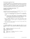
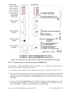
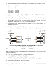
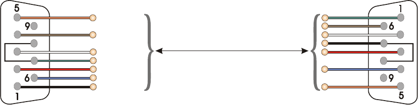
(Looking into
W
ire Terminal Side
of
Cable Connectors)
3 = TXD
6 = DSR
7 = RTS
8 = CTS
4 = DTR
2 = RXD
1 = DCD
5 = GND
To P2 Pin-4
To P2 Pin-2
To P2 Pin-7
To P2 Pin-3
To P2 Pin-6
To P2 Pin-5
To P2 Pin-1
PC
9-Pin Female
“D” Connector
P1
C
W u
/C
W EFM
9-Pin Female
“D” Connector
P2
3 = TXD
6 = DSR
7 = RTS
8 = CTS
4 = DTR
2 = RXD
1 = DCD
5 = GND
or
vice
versa
Figure D3 - (Internal Radio/Modem Configuration) BBI P/N 392843-01-3
Full-duplex Null Modem Cable Diagram
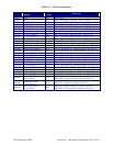
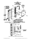
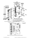
D1.1.3 Installing an Internal MDS Transnet OEM Radio
MDS Transnet OEM Radio is provided (for user installation) in a kit consisting of the
following components:
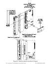
• 6-32 x .188” Pan Head Screw (Qty. 4) - Fig. D4 Reference = 1
• 6-32 x .313” F/F Standoff (Qty. 4) - Fig. D4 Reference = 2
• 6-32 x .250” Pan Head Screw (Qty. 4) - Fig. D4 Reference = 3
• MDS Transnet Radio Cable (with Nut and Washer- Fig. D4 Reference = 4
• Swaged Standoff (Qty 4) - Built into CPU/System Controller Bd. - Fig. D3 Reference = E
• MDS Transnet Radio Module - Fig. D5 Reference = 5