


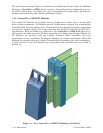
1-12 / Introduction CI-ControlWave EFM
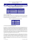
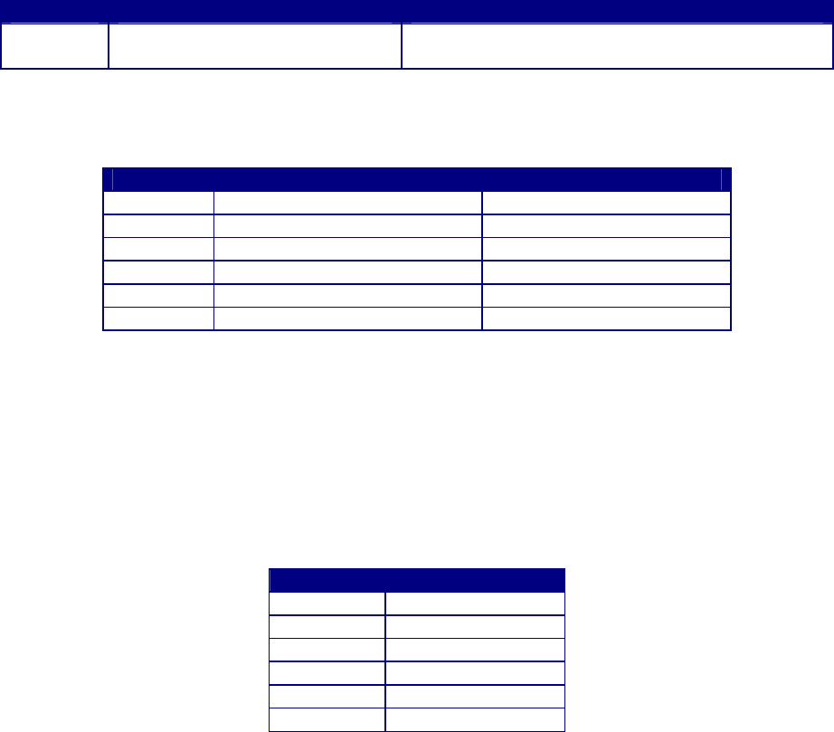
Table 1-3 - Assignment of CPU Bd. Switch SW1
Force Recovery Mode
Switch Function Setting
SW1-3 Force Recovery Mode
ON = Force recovery mode (via CW Console)
OFF = Recovery mode disabled
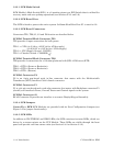
Table 1-4 - Assignment of CPU Module Switch SW3
COM3 -
Loopback & Termination Control
Switch RS-485 Function Setting
SW3-1 TX+ to RX+ Loopback ON - Only for Diagnostics
SW3-2 TX- to RX- Loopback ON - Only for Diagnostics
SW3-3 100 Ohm RX+ Termination ON - End Nodes Only
SW3-4 100 Ohm RX- Termination ON - End Nodes Only
SW3-7 RX+ Bias (End Node) ON - End Nodes Only
SW3-8 RX- Bias (End Node) ON - End Nodes Only
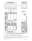
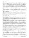
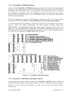
1.3.2.5 CPU Module LEDs
ControlWave EFM CPU Modules have six (6) LEDs on the CPU Board. Units equipped
with an optional Ethernet Port have two (2) additional LEDs (situated on the Ethernet RJ-
45 connector). Table 1-5 provides CPU Module LED assignments. An ON LED indicates an
associated transmit (TX) or receive (RX) activity.
Table 1-5 - Assignment of CPU Module LEDs
LED Ref. LED Function
C1 TX COM1
C1 RX COM1
C2 TX COM2
C2 RX COM2
C3 TX COM3
C3 RX COM3
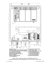
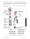
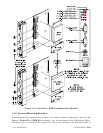
1.3.3 System Controller Module (SCM)
The System Controller Module (SCM) plugs into the system’s Backplane Board slot #1
(Connector P1 - a 44-pin female non-keyed header). The front of the SCM contains two
pluggable terminal blocks for external, input power (TB1) and RTD (TB2 - future) connec-
tions. An RJ-45 connector provides the interface to a remote Display/Keypad Assembly. Two
red LEDs, visible through the front panel, provide for the following status conditions when
lit: WD (Indicates a Watchdog condition has been detected) & IDLE (Indicates that the
CPU has free time at the end of its execution cycle. Normally, it should be ON most of the
time. When the Idle LED is OFF, it indicates that the CPU has no free time, and may be
overloaded). Six status LEDs provide run time status codes.
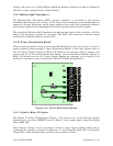
SCMs contain a DC to DC power supply that generates a +3.3Vdc supply for the entire unit,
i.e., the CPU and various I/O Modules that plug into the Backplane Board. Also contained
on the SCM is the sequencer circuit that monitors the external power supply as well as the
logic supplies (3.3Vdc and 1.8Vdc on the CPU Board). The sequencer circuit has a
reset/early power fail warning controller that is utilized by the CPU Board to generate a
master reset (MRESET) to the rest of the system and to generate a power fail interrupt to
the CPU.