


CI-ControlWave EFM Appendix F / F-27
F.6.2.4 Alarm Configuration (Accessed via Meter Run I/O Configuration)
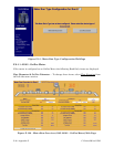
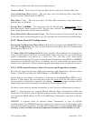
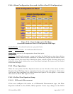
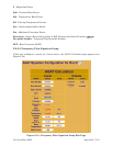
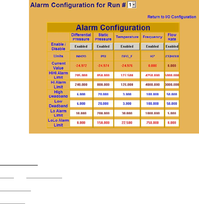
Figure F-17 - Alarm Configuration Web Page
(Accessed from Meter Run I/O Configuration Web Page)
Enable/Disable
- the alarm function on a per point basis.
Units
and Current Value - are read from the I/O source.
Alarm Limit
- are set via the appropriate alarm limit point.
Deadband
- dead bands represent a range just below the high limits or just above the low
limits in which the alarm variable remains in an alarm state, despite the fact that its value
no longer exceeds the alarm limit. Should the alarm variable rapidly fluctuate above and
below the alarm limit (without the use of dead band settings), the system will be flooded
with alarm messages.
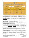
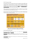
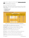
F.6.3 Flow Equations
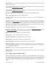
When the user pushes the Flow Equation button (on the left side of the menu) the Flow
Equation Setup Web Page that is appropriate for the meter type will appear. If the meter
type has not been configured, the screen shown for Figure F-12 will appear. A user must
then select the Meter Run Type to be used.
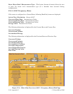
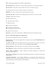
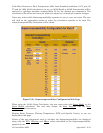
F.6.3.1 Orifice Flow Equation Setup
F.6.3.1.1 Differential Measurement
If the user configures the meter as a Differential Measurement type, the Flow
Equation defaults to the AGA3 (1985) equation. Users may change to the AGA3