


CI-ControlWave EFM Appendix C - Hardware Installation Guide / C-3
Step 1. Hardware Configuration (Continued)
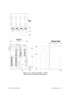
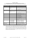
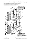
2. Remove the System Controller Module (SCM) and after configuring its configuration
jumpers, install it in chassis slot 1, i.e., the first slot from the left end of the Base
Assembly Chassis (see Section 2.3.2).
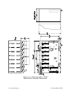
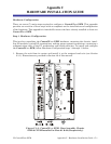
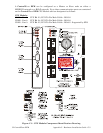
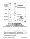
JP5, JP6, JP7, JP8 & JP9
1-to-2 Installed = 12V Bulk System
2-to-3 Installed = 6V Bulk System
P1
1
1
2
JP9
JP8
JP6
JP5
JP7
1
1
1
CR27
CR26
CR25
CR24
(Red)
I DLE LED
(Red)
Sta us LEDs
TB1
Input Power
Connector
(Red)
WATCHDOG LED
TB2
RTD Interface
Connector
P2
MVT Interface
Connector
J2
Display Intf.
Connector
1A
J2
RJ- 4 5
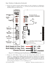
TB 1- 1
TB 1- 2
TB 1- 3
(+4.5/4.9Vdc to +16.0Vdc for +6V supply)
+VIN (+9.6/10.3Vdc to +16.0Vdc for +12V supply)
-VIN (Supply Ground)
Chassis Ground (CHASSIS)
+VIN
1
3
-VIN
CHASSIS
Bulk Supply #1 Pos. Term.
Bulk Supply #1 Neg. Term.
Chassis Ground
SW1 = Mode Switch
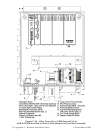
Figure C-2 - SCM Component Identification and TB1 Wiring Diagram
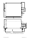
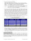
3. Remove the CPU Module. Make sure that the Lithium Backup Battery has been
enabled, i.e., Backup Battery Board Jumper JP1 should be installed (on its jumper
posts). After configuring the CPU Module’s DIP-Switches (see Section 2.3.3), install it
into ControlWave EFM Base Assembly, chassis slot 2, i.e., the second slot from the left
end of the Base Assembly Chassis. Tables C-1, C-2 and C-3 provide an overview of
switch settings (see Tables C-1, C-2, C-3 and Figure C-3).