


2-8 / Installation & Operation CI-ControlWave EFM
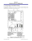
2.3.1 Mounting the ControlWave EFM Enclosure
When mounting one of these units, it is to be positioned in accordance with the following
restrictions:
- The unit is to be positioned vertically with the Multivariable Transducer (MVT) at its
base and is to be mounted to a wall or a vertical 2” pipe (clamed at the rear of the unit
via two clamps and four bolts). If used, the 2” pipe is to be anchored in cement (deep
enough to conform to local building codes associated with frost considerations). The
basic unit measures 14.55” in height by 13” in width by 6.875” in depth. A Mul-
tivariable Transducer adds 2.8” to the unit’s height. See Figures 2-3 and 2-4.
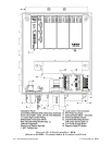
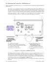
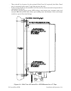
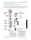
(1) 1” NPT Conduit Hub (2) Local Port D-Type Jack
(3) RTD Cable Assembly or Sealing Plug Male D-Type Jack or
(5) 5” Liquid Tight Conduit Fitting or Plug Circular Female Jack
(7) Solderless Ground Lug (4) Battery Ventilation Assembly
(8) Multivariable Transducer (6) Ant. Cable Fitting, Polyphaser,
or Plug
Figure 2-3 - ControlWave EFM Bottom View
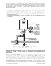
- The Multivariable Transducer (MVT) is bolted to a process manifold which in-turn is
connected to the main (meter run) directly or via two pipes (see Figures 2-5 - 2-7).
- The unit must be positioned so that the front of the assembly is visible and the unit is
accessible for service, i.e., installing an option or replacement of the Lithium Battery,
or installation/removal of any ControlWave EFM Module.
- Make certain that the LCD Display/Keypad is accessible and visible to the on-site
operator.