


CI-ControlWave EFM Introduction / 1-1
Section 1
ControlWave EFM INTRODUCTION
1.1 GENERAL DESCRIPTION
ControlWave EFM electronic flow meters measure differential pressure, static pressure
and temperature for a single run and compute flow for both volume and energy. In addition
to operation in an unprotected outdoor environment, the ControlWave EFC electronic flow
meter provides the following key features.
• ARM processor provides exceptional performance and low power consumption
• Wide operating temperature range: (-40 to +70°C) (-40 to 158°F)
• CPU, SCM & I/O Modules provide LED status Indicators
• Battery backup for the real-time clock and the system’s SRAM is provided by a 3.0V,
300mA-hr lithium coin cell battery located on the CPU Module.
• Very low power consumption
• Integral Multivariable Transducer (MVT) with “smart” performance
• Standard Application Program supports the following Flow calculations:
• Calculates AGA3-1995/NX-19
• AGA3-1992 with selectable AGA8 Gross or AGA8 Detail
• AGA7/NX-19
• AGA7 with selectable AGA8 Gross or AGA8 Detail
• Auto Adjust AGA7/NX-19
• Auto Adjust AGA7 with selectable AGA8 Gross or AGA8 Detail
• Instromet Modbus AGA7 with selectable AGA8 Gross or AGA8 Detail
• Daniel Modbus AGA7 with selectable AGA8 Gross or AGA8 Detail
• Three serial communications ports (Two RS-232 & One RS-485)
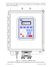
• Four line alphanumeric display (with dual-button Keypad or 25-button Keypad)
• User choice of I/O Modules (AI/AO, AI, DI/DO, HSC and Mixed I/O)
• RTD input
• Nonincendive Class I, Div. 2, Groups C & D Hazardous Locations (see Appendix A)
• RTD input
• Optional Expansion Comm. Modules with/without built-in modem and/or radio
• Chassis Slots 3 and 4 support Expansion Comm. Modules or I/O Modules or one of each
• Optional Display/Keypad System
• Mixed I/O Modules provide cost effective I/O for small RTU applications
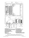
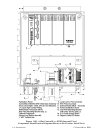
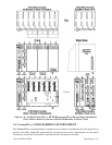
ControlWave EFC electronic flow meters are furnished in a NEMA 3X rated Hoffman®
Enclosure. The flow computer hardware is comprised of a Backplane Board (mounted in a
Housing), a System Controller Module and a CPU Module. Optional Expansion
Communication Modules may reside in Slots 3 and 4 of the Housing in lieu of I/O Modules.
The CPU Module utilizes Sharp’s LH7A400 System-on-Chip Advanced RISC Machine
(ARM) microprocessor with 32-bit ARM9TDMI Reduced Instruction Set Computer (RISC)
Core. In addition to the microprocessor and control logic, the CPU Board includes two RS-
232 communication ports, one RS-485 Communication port, 2MB of battery backed Static
RAM (SRAM), 512kB Boot/Downloader FLASH, 8MB simultaneous read/write FLASH, and
an I/O Bus Connector.
All system modules plug into the Backplane Board (4-Slot or 8-Slot). Each I/O Module
provides the circuitry and field interface hardware necessary to interconnect the assigned
field I/O circuits. Non-isolated power is generated and regulated by the System Controller
Module (SCM) that provides +3.3Vdc for all logic and bulk power for I/O field circuits from
either a bulk 6Vdc or bulk 12Vdc source. +1.8Vdc, used by the ARM microprocessor, is