


C-4 / Appendix C - Hardware Installation Guide CI-ControlWave EFM
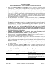
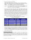
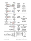
Table C-1 - CPU Bd. Switch SW1 - Force Recovery Mode/Battery Enable
Switch Function Setting - (OFF = Factory Default)
SW1-3
Force Recovery
Mode
ON = Force recovery mode (via CW Console)
OFF = Recovery mode disabled
Note: SCM Switch SW1 can also be used for Force Recovery Mode operation
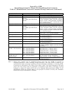
Table C-2 - CPU Bd. Switch SW2 - User Configurations
Note: Except for SW2-4, ON = Factory Default
Switch Function Setting - (ON = Factory Default)
SW2-1 Watchdog Enable
ON = Watchdog circuit is enabled
OFF = Watchdog circuit is disabled
SW2-2
Lock/Unlock
Soft Switches
ON = Write to Soft Switches and FLASH files
OFF = Soft Switches, configurations and FLASH files are locked
SW2-3
Use/Ignore
Soft Switches
ON = Use Soft Switches (configured in FLASH)
OFF = Ignore Soft Switch Configuration and use factory defaults
SW2-4
Core Updump
See Section 3.6
ON = Core Updump Disabled
OFF = Core Updump via Mode Switch (SW1) on SCM
SW2-5 SRAM Control
ON = Retain values in SRAM during restarts
OFF = Force system to reinitialize SRAM
SW2-6
System Firmware
Load Control *
ON = Enable remote download of System Firmware
OFF = Disable remote download of System Firmware
SW2-8
Enable
WINDIAG
ON = Normal Operation (don’t allow WINDIAG to run test)
OFF = Disable boot project (allow WINDIAG to run test)
* = Boot PROM version 4.7 or higher and System PROM version 4.7 or higher
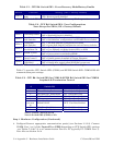
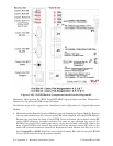
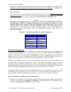
Table C-3 provides CPU Switch SW3 (COM3) and ECOM Switch SW1 COM5/9 RS-485
communication port settings.
Table C-3 - CPU Bd. Switch SW3 for COM3 & ECOM Bd. Switch SW1 for COM5/9
Loopback & Termination Control
Switch
#
RS-485 Function
Switch ON
Setting
1 TX+ to RX+ Loopback ON - Only for Diagnostics
2 TX- to RX- Loopback ON - Only for Diagnostics
3 100 Ohm RX+ Termination ON - End Nodes Only
4 100 Ohm RX- Termination ON - End Nodes Only
5 N/A ON - Slew Rate Enabled
6
(see note
2)
Slow Slew Rate
ISO485 ONLY
ON - Slow Rate Enabled
OFF - Fast Rate Enabled
7 RX+ Bias (End Node) ON - End Nodes Only
8 RX- Bias (End Node) ON - End Nodes Only
Note 1: Closed = Switch set ON
Note 2: Switch SW3 (COM3) = N/A
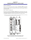
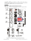
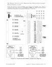
Step 1. Hardware Configuration (Continued)
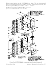
4. Configure/Connect appropriate communication port(s) (see Sections 2.3.3.2). Connect
COMM. Port 1 or 2 of the ControlWave EFM (depending on CPU Switch SW1 settings
- see Tables C-2 & C-3) to a Communication Port of a PC (typically PC COMM. Port 1).
Note: Also see Section 2.4.4.