


CI-ControlWave EFM Specifications / 4-9
Electrical isolation: None
Surge Suppression: 31V Transorb between signal and ground
Meets ANSI/IEEE C37.90-1978
Status Indication: None
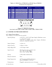
Power Consumption: 200uA or 2mA per HSCSET or HSCRST Input (ON State)
(Jumper Selectable per Point)
(Clock Power Disabled - Subtract 1.1mA @ 3.3V)
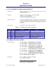
4.5 DIGITAL TO RELAY I/O BOARD SPECIFICATIONS
Digital to Relay I/O Board General Specs.
Terminations: Pluggable - Max. wire size is 14 gauge
Digital to Relay I/O Board Input Requirements
Power Source Range: 3 to 15 Vdc
SSR Input Impedance: 400 Ohms
MOSFET Sink Current: Max. = 20mA (both SSRs in Normally Closed mode)
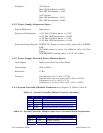
Digital to Relay I/O Board Output Requirements
Contact Ratings: 3 to 60 Vdc
Maximum Current: 3 Amps at 25°C (77°F) or 1.5 Amps at 70°C (158°F)
Maximum ON State: 1.2Vdc
Minimum Current Load: 100mA
4.6 21V POWER SUPPLY BOARD SPECIFICATIONS
21V Power Supply Board General Specs.
Terminations: Pluggable - Max. wire size is 14 gauge
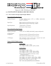
ESD Susceptibility: Field connected circuits meet the requirements of IEC 801-
2 for withstand capability up to 10KV.
EMI Compatibility: Designed to coexist within a shielded enclosure with the
ControlWave EFM electronics. EMI radiation is in-
significant and susceptibility is comparable or superior to
associated electronics.
Transient Susceptibility: Field connected circuits meet the requirements of
ANSI/IEEEC37.90-1998 (Formerly IEEE 472) for surge
withstand capability.