


G-2 / Radio Ready Installation Guide CI-ControlWave EFM
G2.1 RADIO INSTALLATION
DANGER
Radios provided by Bristol, Inc. for use in the ControlWave EFM
Electronic Flow Meters are approved for use in Class I, Division 2, Groups
A, B, C & D hazardous locations. Radios may also be used in non-
hazardous locations. The installer must be familiar with hazardous
location installation guidelines before installation or maintenance is
undertaken. Do not begin radio installation or service to the ControlWave
EFM unless the area is known to be non-hazardous.
NOTE
Only the external radios listed on page 1 of this document may be used in
Class I, Division 2, Groups A, B, C & D hazardous locations! Use of other
external radios in Class I, Division 2, Groups A, B, C & D hazardous
locations is not allowed!
AVOID OPERATING EQUIPMENT DURING AN ELECTRICAL STORM. AN
IMPULSE SUPPRESSOR MAY SAVE EQUIPMENT FROM DANGER, BUT
SHOULD NOT BE CONSIDERED AS BEING SAFE FOR PERSONNEL.
G2.1.1 Installation of a Radio into a Radio Ready ControlWave EFM
Radio Ready ControlWave EFM Electronic Flow Meters contain all the hard-ware
required (except the radio and securing hardware) to accommodate installation and
operation of the radio option.
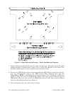
1. Open the Instrument Front Cover.
2. Remove the Radio Mounting Bracket by removing the two 10-32 x 3/8 Pan Head Screws
that secure it to the Fabrication Panel.
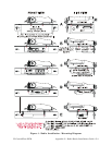
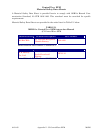
3. Using the mounting hardware provided with the radio, mount and secure the radio to
the Radio Mounting Bracket removed in step 2 (see Figures 1 & 2).
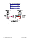
4. Re-install the Radio Mounting Bracket to the Fabrication Panel using the two 10-32 x
3/8 Pan Head Screws that were removed in step 2.
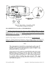
5. Connect the radio’s RF cable to the radio. The other end of the radio’s internal RF cable
should already be installed onto either a Polyphaser or a RF Bulk Head/Antenna
Interface connector.
6. Connect the user supplied antenna cable to either the Polyphaser or Bulk Head antenna
cable connector jack on the bottom of the ControlWave EFM (see Figure 3).