


CI-ControlWave EFM Service / 3-5
3.2.9 Removal/Replacement of a 21V Power Supply Board
1. If the ControlWave EFM is running, place any critical control processes under
manual control (as required).
2. Unplug wiring harnesses from 21V Power Supply Board connectors TB1 and TB2.
3. Slide the 21V Power Supply Board toward the front of the unit and remove it from
its Snap Track Holder.
4. To replace a 21V Power Supply Board, slide it into its Snap Track Holder. Replace
wiring harness connectors TB1 and TB2.
5. Apply power (if necessary) and test the unit.
3.2.10 Removal/Replacement of a Digital to Relay I/O Board
1. If the ControlWave EFM is running, place any critical control processes under
manual control and shut down the unit by disconnecting power to the System
Controller Module (SCM).
2. Unplug wiring harnesses from Digital to Relay I/O Board connector J1.
3. Slide the Digital to Relay I/O Board toward the front of the unit and remove it from
its Snap Track Holder.
4. To replace a Digital to Relay I/O Board, slide it into its Snap Track Holder. Replace
wiring harness connector J1/P1.
5. Apply power (replace SCM Power Connector - TB1) and test the unit.
3.2.11 Removal/Replacement of an External Radio/Modem
1. If the ControlWave EFM is running, place any critical control processes under
manual control and shut down the unit by disconnecting power to the System
Controller Module (SCM).
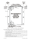
2. Remove the Sealed Lead-acid Battery (if present) (see Section 3.2.7).
3. Disconnect (unplug) all connectors (power and interface) from the Radio/Modem.
4. Remove the mounting screws from the bottom (inside) of the Battery Mounting
Bracket and remove the Radio/Modem (with Mounting Plate if present).
5. Replace the Radio/Modem in the reverse order from which it was removed.
6. Apply power (replace SCM Power Connector - TB1) and test the unit.
3.3 TROUBLESHOOTING TIPS
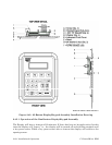
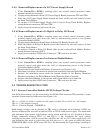
3.3.1 System Controller Module (SCM) Voltage Checks
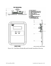
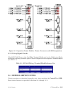
One bulk power source can be connected to the SCM. SCM connector TB1 provides 3 input
terminal connections for bulk power (see Figure 3-2):
TB1-1 = (+VIN) (+4.5/4.9V to +16V dc for +6V supply) (+9.6/10.3V to +16V dc for +12V supply)
TB1-2 = (-VIN) (Supply Ground)
TB1-3 =
Chassis Ground - CHASSIS (;)
Bulk supply voltages can be checked at TB1 using a voltmeter or multimeter. SCM’s are
factory configured for use with a nominal 6Vdc or 12Vdc bulk power supply. The maximum
and minimum input power switch-points can be tested with the use of a Variable dc Power
Supply connected between TB1-1 (+) and TB1-2 (-). By increasing the input voltage
(starting at less than +4.5Vdc or less than +9.6Vdc) for +6V or +12V units respectively, you
can determine the point at which the unit will turn on, i.e., the point at which the green
PWRGOOD LED on the SCM comes ON (Vt+). By decreasing the input voltage (starting at