


CI-ControlWave EFM Specifications / 4-5
Note
2
: 2.5 ohm uncompensated series resistance with
Inductors
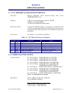
Terminations: Pluggable - Max. wire size is 14 gauge
Data Transfer: 8 Bit Wide bus access
4.4.2 Non-isolated Digital Input/Output Module
Non-isolated Digital Inputs
Number of Inputs: 12 DI individually jumper configurable for 2mA or 60uA
Internally Sourced (Dry Contact) operation
Input Filtering: 15 milliseconds
Input Current: Jumper configured for 2mA or 60uA nominal
‘0’ State Voltage: below 1.5V
‘1’ State Voltage: above 1.5V
Bus Access: Eight Bits Wide
Electrical Isolation: None
Surge Suppression: 31V Transorb between signal and ground
Meets ANSI/IEEE C37.90-1978
Status Indication: 12 LEDs (one per point)
Non-isolated Digital Outputs
Number of Outputs: 4 DO
Output Configuration: Open Drain (Externally Powered)
Maximum Load Current: 100mA @ 31Vdc
Bus Access: Eight Bits Wide
Electrical Isolation: None
Surge Suppression: 31V Transorb between signal and ground
Meets ANSI/IEEE C37.90-1978
General DI/DO Module Specs.
Power Consumption:
Status LEDs Disabled
1.3mA @ 3.3Vdc: 12DIs OFF, CLK stopped
2.1mA @ 3.3Vdc: 12DIs ON @ 66uA, CLK stopped
25.3 @ 3.3Vdc: 12DIs ON @ 2mA, CLK stopped
3.6mA @ 3.3Vdc: 12DIs OFF, CLK active