


CI-ControlWave EFM Introduction / 1-13
The power supply operates from +4.5/+4.9 to +16Vdc or +9.6/10.3 to +16Vdc with the
nominal input supply configuration (+6V or +12V) user configured via on-board jumpers. A
supervisory circuit monitors the incoming power and the supply voltages. The isolated
supplies are shut down when the incoming voltage drops below +4.5V for a +6V system or
+9.6V, for a +12V system.
An external battery monitor is composed of an Analog to Digital Converter (ADC) and
interface circuitry.
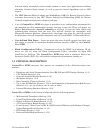
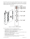
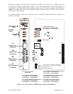
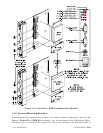
JP5, JP6, JP7, JP8 & JP9
1-to-2 Installed = 12V Bulk System
2-to-3 Installed = 6V Bulk System
JP1 - Factory Configured
(Not Shown)
JP5 - Power Fail Trip Point Selection
1-to-2 Installed = 12V Bulk System
2-to-3 Installed = 6V Bulk System
JP6 - Supply Shutdown Trip Point Selection
1-to-2 Installed = 12V Bulk System
2-to-3 Installed = 6V Bulk System
JP7 - 1.2V Reference Source Current Selection
1-to-2 Installed = 12V Bulk System
2-to-3 Installed = 6V Bulk System
JP8 - Supply Shutdown Trip Point Hysterisis
1-to-2 Installed = 12V Bulk System
2-to-3 Installed = 6V Bulk System
JP9- Power Fail Trip Point Hysterisis
1-to-2 Installed = 12V Bulk System
2-to-3 Installed = 6V Bulk S
y
ste
m
P1
1
1
2
JP9
JP8
JP6
JP5
JP7
1
1
1
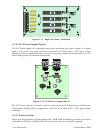
CR27
CR26
CR25
CR24
(Red)
I D LE LED
(Red)
Sta us LEDs
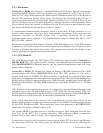
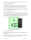
TB1
Input Power
Connector
(Red)
WATC HDO G LED
TB2
RTD Inte rfa c e
Connector
P2
MVT Interface
Connector
J2
Display Intf.
Connector
1A
J2
RJ- 45
TB 1- 1
TB 1- 2
TB 1- 3
(+4.5/4.9Vdc to +16.0Vdc for +6V supply)
+VIN (+9.6/10.3Vdc to +16.0Vdc for +12V supply)
-VIN (Supply Ground)
Chassis Ground (CHASSIS)
SW1 = Mode Switch
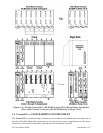
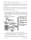
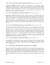
Figure 1-6 - ControlWave EFM System Controller Module