


CI-ControlWave EFM Service / 3-7
ControlWave EFM LED designations are provided in Table 3-1.
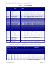
Table 3-1 - LED Assignment
Module
LED
Name
LED
Color
Function
SCM * IDLE Red ON = Idle
SCM * WD Red ON = Watchdog Condition - OFF = Normal
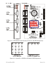
SCM 6 STATUS Red See Table 3-2 & Figure 3-2
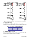
CPUM C1 RX (Comm 1) Red ON = RX Activity (Top-Left - see Fig. 3-4)
CPUM C1 TX (Comm 1) Red ON = TX Activity (Top-Right -see Fig. 3-4)
CPUM C2 RX (Comm 2) Red ON = RX Activity (Middle-Left - see Fig. 3-4)
CPUM C2 TX (Comm 2) Red ON = TX Activity (Middle-Right -see Fig. 3-4)
CPUM C3 RX (Comm 3) Red ON = RX Activity (Bottom-Left - see Fig. 3-4)
CPUM C3 TX (Comm 3) Red ON = TX Activity (Bottom-Right -see Fig. 3-4)
ECOM1 C1 RX (Comm 4) Red ON = RX Activity (Top-Left - see Fig. 3-6)
ECOM1 C1 TX (Comm 4) Red ON = TX Activity (Top-Right -see Fig. 3-6)
ECOM1 C2 RX (Comm 5) Red ON = RX Activity (2
nd
from Top-Left - see Fig. 3-6)
ECOM1 C2 TX (Comm 5) Red ON = TX Activity (2
nd
from Top-Right -see Fig. 3-6)
ECOM1 Radio RX (Comm 6) Red ON = RX Activity (3
rd
from Top-Left - see Fig. 3-6)
ECOM1 Radio TX (Comm 6) Red ON = TX Activity (3
rd
from Top-Right -see Fig. 3-6)
ECOM1 Modem RX (Comm 7) Red ON = RX Activity (Bottom-Left - see Fig. 3-6)
ECOM1 Modem TX (Comm 7) Red ON = TX Activity (Bottom-Right -see Fig. 3-6)
ECOM2 C1 RX (Comm 8) Red ON = RX Activity (Top-Left - see Fig. 3-6)
ECOM2 C1 TX (Comm 8) Red ON = TX Activity (Top-Right -see Fig. 3-6)
ECOM2 C2 RX (Comm 9) Red ON = RX Activity (2
nd
from Top-Left - see Fig. 3-6)
ECOM2 C2 TX (Comm 9) Red ON = TX Activity (2
nd
from Top-Right -see Fig. 3-6)
ECOM2 Radio RX (Comm 10) Red ON = RX Activity (3
rd
from Top-Left - see Fig. 3-6)
ECOM2 Radio TX (Comm 10) Red ON = TX Activity (3
rd
from Top-Right -see Fig. 3-6)
ECOM2 Modem RX (Comm 11) Red ON = RX Activity (Bottom-Left - see Fig. 3-6)
ECOM2 Modem TX (Comm 11) Red ON = TX Activity (Bottom-Right -see Fig. 3-6)
DI/OM
Input (12 LEDs)
(1 Per Point)
Red
LED ON = Input is present
LED OFF = Input is not present (see Fig. 3-5)
DI/OM
Output (4 LEDs)
(1 Per Point)
Red LED ON = Output is ON (see Fig. 3-5)
HSCM
INPUT (4 LEDs)
(1 Per Point)
Red
LED ON = Input activity on input is present
LED OFF = No activity on input (see Fig. 3-5)
* = see Figure 3-2
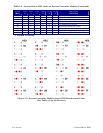
Table 3-2 - System Status LED Codes on System Controller Module
Status
(Hex)
LED
6
LED
5
LED
4
LED
3
LED
2
LED
1
Indication
Definition
00 0 0 0 0 0 0 Application Running
01 0 0 0 0 0 1 Unit in Diagnostic Mode
03 0 0 0 0 1 1 Unit Running Diagnostics
04 0 0 0 1 0 0 Flash XSUM Error
05 0 0 0 1 0 1 Error Initializing Application Device
07 0 0 0 1 1 1 Flash Programming Error
08 0 0 1 0 0 0
Using Factory Defaults *
09 0 0 1 0 0 1
Battery Failure Detected *
0A 0 0 1 0 1 0 Currently Loading the Boot Project
0B 0 0 1 0 1 1 System Initialization in Progress
10 0 1 0 0 0 0 Waiting in Recovery Mode