


CI-ControlWave EFM Appendix C - Hardware Installation Guide / C-1
Appendix C
HARDWARE INSTALLATION GUIDE
Hardware Configuration
There are seven (7) main steps required to configure a ControlWave EFM. This appendix
provides an overview of these steps with an emphasis on the installation and configuration
of the hardware. This appendix is intended for users who have already installed at least one
ControlWave EFM.
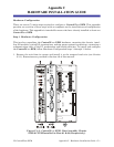
Step 1. Hardware Configuration
This involves unpacking the ControlWave EFM hardware, mounting the chassis, instal-
ling I/O modules, wiring I/O terminations, making proper ground connections, connecting a
communication cable to the PC workstation and setting switches. To install and configure
the ControlWave EFM, follow Hardware Configuration steps 1 through 11 below:
1. Remove the unit from its carton and install it at the assigned work site (see Section
2.3.1). Dimensions are provided in Section 4.6 of this manual.
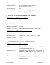
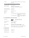
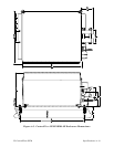
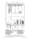
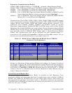
Figure C-1A - ControlWave EFM - Base Assembly Chassis
SCM & CPUM Installed in Slots #1 & #2 (Respectively)