


CI-ControlWave EFM Installation & Operation / 2-13
heating (e.g., with a rose-bud torch) it electrically insulates and increases the strength of
the pipe stand. See Bristol Specification Summary F1670SS-0a for information on PGI
Direct Mount Systems and Manifolds.
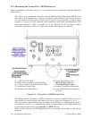
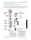
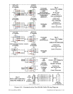
2.3.2 System Controller Module (SCM) Configuration
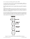
System Controller Module’ (SCM) configuration jumpers must be set to configure bulk
power (+6Vdc or +12Vdc nominally) and to enable or disable the Power Good LED (see
Figure 2-8). The SCM is installed in Backplane slot #1 (see Figure 2-2). Slot #1 is the first
slot, counting left to right, and provides 44-pin female interface connector P1.
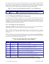
JP5, JP6, JP7, JP8 & JP9
1-to-2 Installed = 12V Bulk System
2-to-3 Installed = 6V Bulk System
JP1 - Factory Configured
(Not Shown)
JP5 - Power Fail Trip Point Selection
1-to-2 Installed = 12V Bulk System
2-to-3 Installed = 6V Bulk System
JP6 - Supply Shutdown Trip Point Selection
1-to-2 Installed = 12V Bulk System
2-to-3 Installed = 6V Bulk System
JP7 - 1.2V Reference Source Current Selection
1-to-2 Installed = 12V Bulk System
2-to-3 Installed = 6V Bulk System
JP8 - Supply Shutdown Trip Point Hysterisis
1-to-2 Installed = 12V Bulk System
2-to-3 Installed = 6V Bulk System
JP9- Power Fail Trip Point Hysterisis
1-to-2 Installed = 12V Bulk System
2-to-3 Installed = 6V Bulk System
P1
1
1
2
JP9
JP8
JP6
JP5
JP7
1
1
1
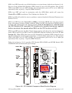
CR27
CR26
CR25
CR24
(Red)
IDLE LED
(Red)
Sta us LEDs
TB1
Input Power
Connector
(Red)
WATC HDO G LED
TB2
RTD Inte rfa c e
Connector
P2
MVT Interface
Connector
J2
Display Intf.
Connector
1A
J2
RJ- 45
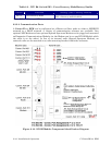
TB1 - 1
TB1 - 2
TB1 - 3
(+4.5/4.9Vdc to +16.0Vdc for +6V supply)
+VIN (+9.6/10.3Vdc to +16.0Vdc for +12V supply)
-VIN (Supply Ground)
Chassis Ground (CHASSIS)
SW1 = Mode Switch
Figure 2-8 - System Controller Module Component Identification Diagram