


C-8 / Appendix C - Hardware Installation Guide CI-ControlWave EFM
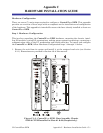
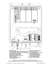
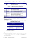
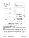
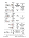
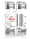
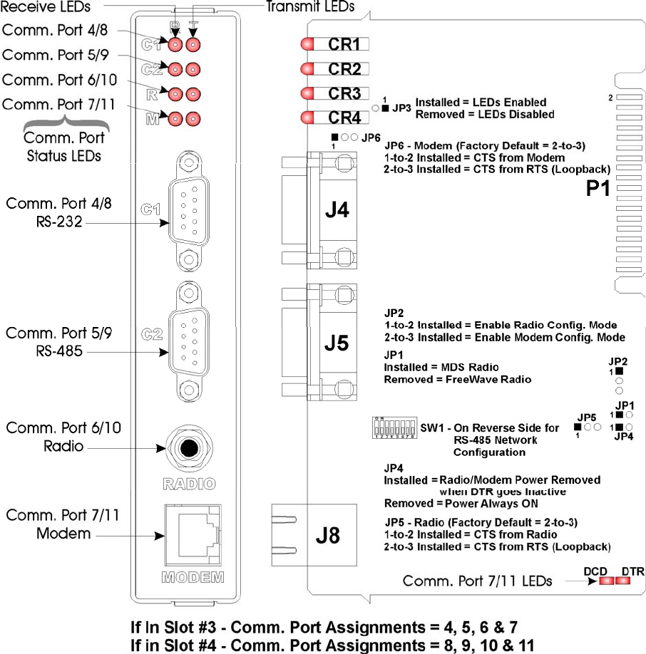
Figure C-4B - ECOM Module Component Identification Diagram #2
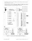
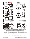
Microwave Data System Inc. MDS TransNET OEM™ Spread Spectrum Data Transceiver:
Operates in the 902 to 928 MHz range (20 miles).
Installation steps below support user installation and configuration of a Spread Spectrum
Modem.
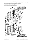
• Mount the radio (Spread Spectrum Modem) onto the Expansion Comm. Module. Remove
the nut and washer from the internal coaxial RF cable supplied with the ECOM Module.
Remove the plug from the front of the ECOM Cover and insert the in-ternal coaxial RF
cable’s SMA connector (straight end with flat area on top) through the rear of the
ECOM Cover. Install the washer and nut to secure the internal coaxial RF cable to the
front of the ECOM Cover. Install the other end of the internal coaxial RF cable to the
radio’s RF antenna connector. Install the Expansion Comm. Module into Slot 3 or 4 of a
base ControlWave EFM. Install the user supplied coaxial RF cable between the ECOM
Cover’s SMA connector and the remote antenna.