


CI-ControlWave EFM Installation & Operation / 2-35
signals, or relay contacts. A serial EEPROM contains HSC Board serialization data. Each
input of the HSCI Module is configured as a 16-bit high-speed counter.
2.3.4.6.1 High Speed Counter Configurations
HSC Modules provide a total of 4 HSC inputs with surge protection. HSC Module Con-
figuration Jumpers W1 through W14 must be set per Table 2-10.
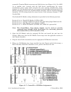
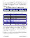
Table 2-10 - Non Isolated High Speed Counter Module Jumper Assignments
Jumper Purpose Notes
W1 - W4 Configures HSC1 through
HSC4 (respectively)
Pins 1-2 installed = Enables HSC Debounce
Pins 2-3 installed = Disabled HSC Debounce
W5 Program Serial EEPROM Factory Use ONLY
W6 LED Enable/Disable Pins 1-2 installed = Enables LEDs Manually
Pins 2-3 installed = Enable LEDs via software
W7 & W8 HSC1 Current Control Pins 1-2 installed = for additional 2mA load
Pins 2-3 installed = 200uA Source no 2mA load
W9 & W10 HSC2 Current Control Pins 1-2 installed = for additional 2mA load
Pins 2-3 installed = 200uA Source no 2mA load
W11 & W12 HSC3 Current Control Pins 1-2 installed = for additional 2mA load
Pins 2-3 installed = 200uA Source no 2mA load
W13 & W14 HSC4 Current Control Pins 1-2 installed = for additional 2mA load
Pins 2-3 installed = 200uA Source no 2mA load
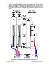
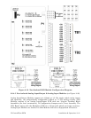
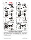
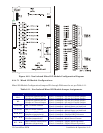
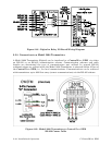
Field wiring assignments are provided in Figure 2-21.
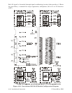
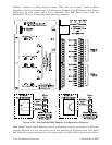
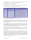
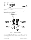
2.3.4.7 Non-isolated Mixed I/O Module (see Figures 2-22 & 2-23)
Non-isolated Mixed I/O Modules provide a total of 6 individually field configurable Digital
Inputs/Outputs, 4 Analog Inputs, 2 High Speed Counter Inputs and 1 optional Analog
Output. I/O circuitry is similar to those utilized on the I/O Modules discussed in sections
2.3.4.4 through 2.3.4.6.
Surge Suppression and signal conditioning is provided for each DI. DO circuits consist of an
open drain MOSFETs and Surge Suppression. Mixed I/O Modules provide internally
sourced DI operation for Dry Contacts pulled internally to 3.3Vdc when the field input is
open. Each DI is protected with a surge suppressor. DI filtering is 15 milliseconds. DOs are
composed of open drain MOSFETs and surge suppressors.
Mixed I/O Module AIs are independently configurable for 4-20mA or 1-5 Vdc single ended
operation. Each AI signal is channeled through signal conditioning circuitry (that provides
a 2 Hertz low pass filter), a transorb for surge suppression, multiplexer, and an A-to-D
Converter (ADC).
Non-isolated Mixed I/O Modules support a total of 2 HSC inputs provided with surge
suppression, bandwidth limiting and 20 microsecond (50kHz) filtering. HSC inputs may be
individually field configured with contact debounce circuitry enabled or disabled and for
2mA or 200uA (low power) operation. HSCs are supported by signal conditioning circuitry
consisting of a debounce circuit followed by a one shot pulse circuit that generates a 65
microsecond ±10% pulse and limits the maximum frequency of an input signal to 15kHz.
Field inputs can be driven signals, or relay contacts. Each input of the HSCI Module is
configured as a 16-bit high-speed counter.