


CI-ControlWave EFM Installation & Operation / 2-31
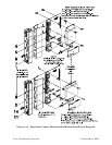
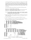
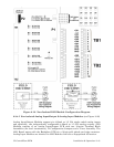
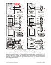
Figure 2-19 - Non-Isolated DI/O Module Configuration Diagram
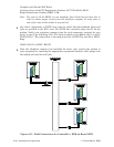
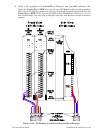
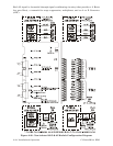
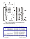
2.3.4.5 Non-isolated Analog Input/Output & Analog Input Modules (see Figure 2-20)
Analog Input/Output Modules support six 4-20mA or 1-5 Vdc single ended analog inputs
and optionally, two independently configurable 4-20mA or 1-5 Vdc analog outputs. AI/O
Modules consists of an Analog Input/Output PCB with two 10-point Terminal Block
Assemblies (for local termination), 12 Configuration Jumpers and a Cover Assembly. The
AI/O Board mates with the Backplane PCB via a 36-pin gold plated card edge connector.
Analog Input Modules are identical to AI/O Modules but have a depopulated AO section.