


3-2 / Service CI-ControlWave EFM
3.2.2 Removal/Replacement of the Bezel Assembly
Before I/O Modules can be removed, the Bezel Assembly, which covers them, must be
removed.
1. Grasp the sides of the Bezel Assembly and gently lift it up and then pull it out and
off its associated I/O Module Covers.
2. To replace the Bezel Assembly, first align the latches (left and right, top and bottom)
with the associated I/O Module Cover notches. Press the Bezel in so that its latches
can be captured by the notches, and slide it downward until it seats and is secured.
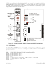
3.2.3 Removal/Replacement of the CPU Module
1. If the ControlWave EFM is running, place any critical control processes under
manual control and shut down the unit by disconnecting power to the System
Controller Module (SCM).
2. Disconnect any CPU Module Communication Cables, making sure they are iden-
tified so they can be returned to their assigned Comm. Ports.
3. Press down on the Cover’s built-in top latch (with one hand) and up on the Cover’s
built-in bottom latch (with the other hand).
4. Carefully slide the CPU Module out of the front of the Housing. If binding occurs,
gently rock the module up and down to free it.
5. To replace a CPU Module, power must be off. Carefully align the CPU Module with
ControlWave EFM Slot 2 and insert the unit into the Housing. When the assembly
is fully seated, its cover should be latched to the Housing.
6. Replace any Comm. Cables and then apply power and test the unit.
3.2.4 Removal/Replacement of the System Controller Module
1. If the ControlWave EFM is running, place any critical control processes under
manual control and shut down the unit by disconnecting power to the System
Controller Module (SCM).
2. Unplug the SCM’s modular connectors.
3. Press down on the Cover’s built-in top latch (with one hand) and up on the Cover’s
built-in bottom latch (with the other hand).
4. Carefully slide the SCM Module out of the front of the Housing. If binding occurs,
gently rock the module up and down to free it.
5. To replace the SCM Module, power must be off. Carefully align the SCM Module
with ControlWave EFM Slot 1 and insert the unit into the Housings. When the
assembly is fully seated, its cover should be latched to the Housing.
6. Replace Power and Watchdog cables and then apply power and test the unit.
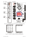
3.2.5 Removal/Replacement of an I/O Module
1. If the ControlWave EFM is running, place any critical control processes under
manual control and shut down the unit by disconnecting power to the System
Controller Module (SCM).
2. Remove the applicable Bezel Assembly (see Section 3.2.2).
3. Unplug local termination cable headers from I/O Module connectors TB1 and TB2 or
remote termination cables headers from connectors P3 and P4 and set the cables
aside. Make sure these cables are identified so they can be returned to their
assigned connectors.