


2-34 / Installation & Operation CI-ControlWave EFM
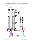
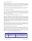
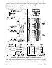
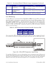
Modules consists of a High Speed Counter PCB with two 10-point Terminal Block
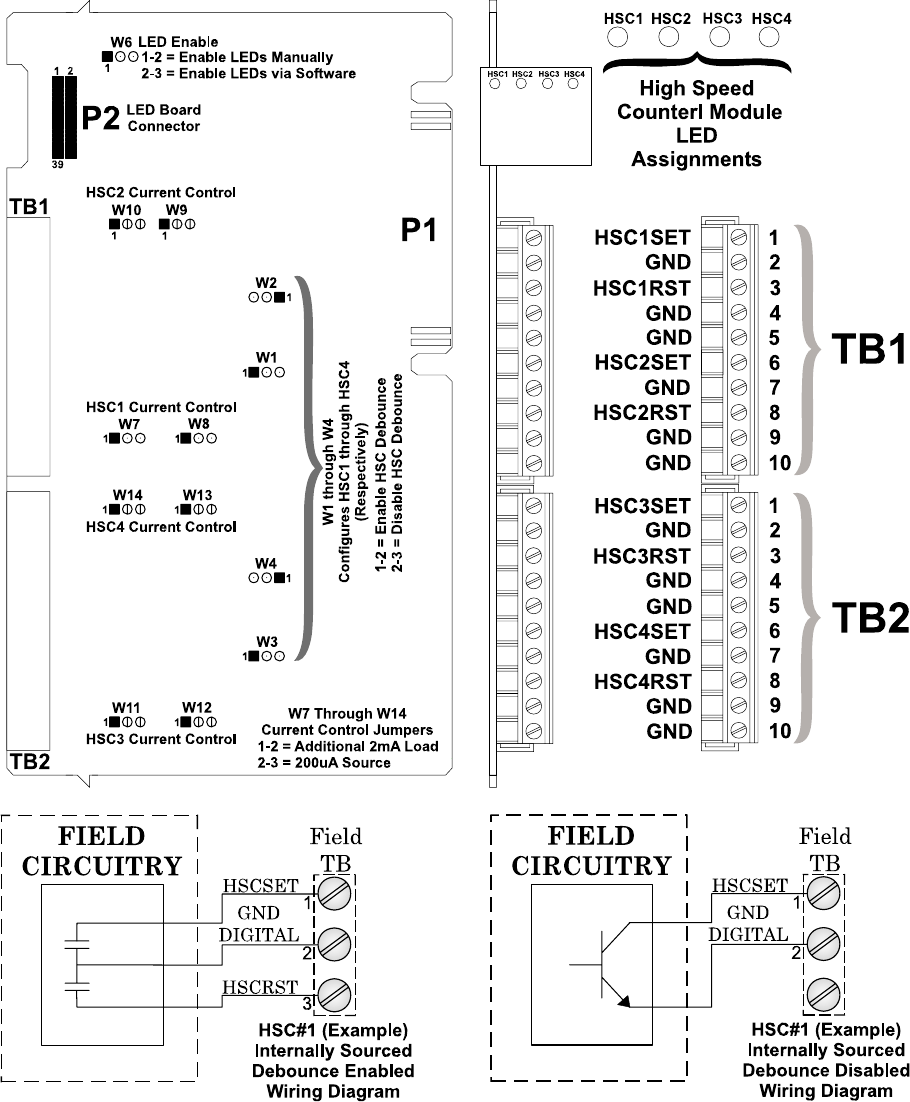
Assemblies (for local termination), 14 Configuration Jumpers, an LED Board with 4 Status
LEDs (one for each point) and a Cover Assembly. The HSC Board mates with the
Backplane PCB via a 36-pin gold plated card edge connector.
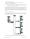
Figure 2-21 - Non Isolated HSC Module Configuration Diagram
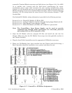
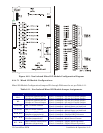
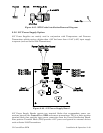
High Speed Counter Input Modules contain conditioning circuitry consisting of a debounce
circuitry followed by a one shot pulse circuit that generates a 65 microsecond ±10% pulse
and limits the maximum frequency of an input signal to 15kHz. Field inputs can be driven