


2-46 / Installation & Operation CI-ControlWave EFM
Bulk +6/12Vdc Supply Current = CPU* + Sum of all ECOM Modules, I/O Modules, optional
Boards & Optional External Modem/Radio
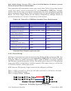
This summation will accommodate steady state current draw. Table 2-16 provides detailed
steady state power current requirements for each ControlWave EFM Base Assembly
module. Note: In the case of an external modem/radio, the unit’s manufacturer provides
power consumption specifications. Power requirements for the optional Digital to Relay I/O
Board, 21V Power Supply Board and the Battery Charger/Power Manager Board are
provided in Sections 4.5, 4.6 and 4.7 (respectively) of this manual.
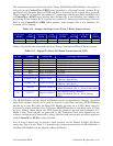
Table 2-16 - ControlWave EFM Base Assembly Power Requirements
COMPONENTS BULK 12Vdc Supply BULK 6Vdc Supply
CPU* = CPU + SCM + Backplane
8.6mA 14mA
Non-Isolated AI/O Module 2.8mA + (47.2mA - VEXT) 5.6mA + (47.2mA - VEXT)
Non-Isolated DI/O Module 12mA 24mA
Non-Isolated HSC Module 5mA 10mA
Non-Isolated Mixed I/O Module
(with optional AO Board)
16.67mA + (24.3mA - VEXT) 34mA + (24.3mA - VEXT)
ECOM Module
(without Modem/Radio)
22mA 45mA
ECOM Module
(with MultiTech Modem)
56mA 112mA
ECOM Module
(with MDS Radio)
277mA 555mA
ECOM Module
(with Modem & MDS Radio)
311mA 622mA
ECOM Module
(with FreeWave Radio)
272mA 545mA
ECOM Module
(with Modem & FreeWave Radio)
306mA 612mA
Note: Current consumption provided in Table 2-15 is based on the standard
Electronic Flow Computer application load.
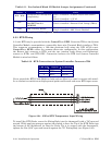
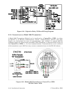
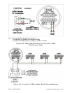
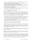
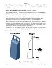
2.3.9.2 Power Wiring
DC Power is interconnected to the System Controller Module (SCM) on Connector TB1. One
Bulk DC supply can be connected to the ControlWave EFM SCM. The Bulk DC supply
(nominally +6Vdc or +12Vdc) connected to TB1-1 (+VIN on SCM) is converted, regulated
and filtered by the SCM to produce +3.3Vdc. This SCM circuit is fused at 1A. The operating
range of the SCM is +4.5/4.9Vdc to +16.0Vdc (nominal +6Vdc input source) or +9.6/10.3Vdc
to +16.0Vdc (nominal +12Vdc input source).
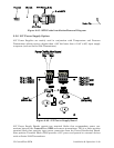
SCM Connector TB1 provides 3 input connections for bulk power as follows:
TB1-1 = (+VIN) (+4.5/4.9V to +16V dc for +6V bulk) (+9.6/10.3V to +16V dc for +12V bulk)
TB1-2 = (-VIN) (Supply Ground)
TB1-3 = Chassis Ground - CHASSIS
Figure 2-34 - SCM (TB1) Typical Wiring Scheme