


51 | NAVISET ADMINISTRATOR 2 USER’S GUIDE
• Communications via both LAN and RS232 are not supported at the same time. The type of
communications link to use to the display must be selected by OSD setting EXTERNAL CONTROL RS-
232C / LAN.
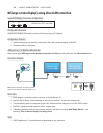
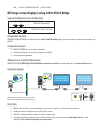
Connecting via a LAN Daisy-chain
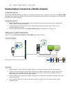
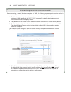
Supported display connection congurations
LAN1 LAN2
RS-232C
RS-232C IN, LAN1 and LAN2
Models that have two RJ45 LAN connections (not including any RJ45 LAN connections on OPS devices) support LAN
daisy-chaining. The RJ45 LAN connection labeled LAN1 should be used as an input to the display from the network.
The other LAN connection labeled LAN2 is the output to connect to the LAN1 on the next display in the daisy chain.
The display functions as a two port LAN hub for LAN trafc.
Important: The LAN hub function only works when AC power is applied to the display and the LAN interface is powered
on. By default the LAN POWER setting is set to turn o when the display enters a standby power mode. This will prevent
communications with other devices along the LAN daisy-chain. To prevent this, change the LAN POWER setting ON via the
OSD. This setting can also be automatically set to ON when the device is added to NaViSet Administrator if the preference
setting is selected - see “Devices” on page 114.
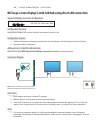
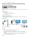
Displays in a LAN daisy-chain that are connected to a LAN network can be addressed in two different ways:
1. Direct (recommended):
Each display in a LAN daisy-chain can also be added to NaViSet Administrator as an individual NEC large-screen
display, rather than as part of a daisy-chain, by adding each display by it’s IP address and Monitor ID.
NaViSet Administrator will communicate directly to each display via it’s IP address.
2. Via Translation:
The rst display in a LAN daisy-chain can act as a host for commands it receives for any of the other displays further
along the daisy-chain. It will translate and forward to the relevant display any commands received via the LAN2
connection sent to it’s IP address, but with Monitor IDs for other displays in the daisy-chain.
In order to do this, the Auto ID function must be successfully performed on the rst display. The Auto ID function is
used to identify all displays along the LAN daisy-chain and assign them sequential Monitor IDs. The rst display in
the LAN daisy-chain stores a table of the IP addresses and assigned Monitor IDs for all of the other displays in the
daisy-chain.
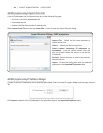
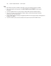
To use this type of addressing, the displays must be added using the Add Single Device dialog and selecting This
is the rst display in a daisy chain. See “Adding NEC large-screen display(s) connected to LAN” on page 27
for more information.
IMPORTANT: Using direct addressing for each NEC large-screen display is highly recommend when using
NaViSet Administrator since it allows simultaneous communications with multiple displays, rather that having
to wait for the rst display to process communications for each display in turn within the daisy-chain.
Therefore when adding NEC large-screen displays that are daisy-chained via LAN, it is recommended
to add them individually by IP address, rather than treating them as a daisy-chain and using the “This
is the rst display in a daisy-chain”.
See the following for more information on using the Auto ID function.