


49 | NAVISET ADMINISTRATOR 2 USER’S GUIDE
Conguring and connecting NEC large-screen displays
NEC large-screen displays can be connected to the network in a variety of ways using RS232 or LAN, depending on
the model.
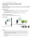
Also, depending on the model, displays can be daisy-chained together using RS232 or LAN cables. Daisy-chaining
displays can simplify cable wiring, and allows more than one display to be controlled from one access connection, as
well as minimizing the lengths and number of cable runs.
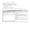
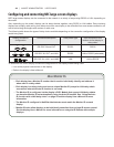
The following table shows the types of daisy-chains available depending on the connection conguration of the display
model being used.
Display connection
conguration
Connection description Daisy-chain type Input connection from
network to rst display in
daisy-chain
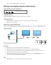
RS-232C
IN
RS-232C
OUT
RS-232C IN and OUT RS232 RS232
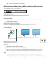
RS-232C
IN
RS-232C
OUT
LAN
RS-232C IN, OUT, and LAN RS232 LAN or RS232 (selectable)
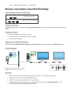
LAN1 LAN2
RS-232C
RS-232C IN, LAN 1 and LAN2 LAN LAN or RS232
To determine the correct display connection conguration for the display models being used:
• Look at the physical connections on the display.
• Refer to the display’s User’s Manual.
About Monitor IDs
• Each display has a Monitor ID number that is used to individually identify and address it
when used in a daisy-chain.
• Each display in a daisy-chain must have a unique Monitor ID (except for LAN daisy-chain
connections where the Auto ID function is not used).
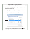
• The Monitor ID is congured via the display’s OSD. Models that support LAN daisy-chains
can have the Monitor ID set automatically using the Auto ID function. See “Using the Auto
ID function with a LAN daisy-chain” on page 52 and the display User’s Manual for more
information.
• The Monitor ID congured in NaViSet Administrator must match the Monitor ID on each
display.
• Monitor IDs also allow displays to be individually controlled from a single IR remote control.
See the display User’s Manual for more information on using the IR Remote with multiple
displays.