


3-44
Rev 1
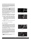
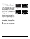
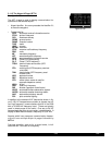
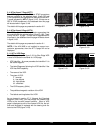
The primary APT 3 page (figure 3-137) follows the run-
way diagram. Runway designation, lighting, and types of
surface for up to five runways are displayed in order of
length, beginning with the longest. Since there are many
times when all of an airport’s runway information does not
fit on one page, additional APT 3 pages are used to dis-
play the data. Remember that a “+” inserted between the
page type and the number (APT+3 in this case) is used to
indicate that there is more than one Airport 3 page.
• The letters “RT” followed by a runway designation
indicate that the runway normally has a right hand
traffic pattern. In figure 3-137, RT 25 31 designates
that runways 25 and 31 have a right hand traffic pat-
tern.
• Runway number designation for both ends of the run-
way.
• Runway lighting availability.
L - runway lighting sunset to sunrise
LPC - runway lighting is pilot controlled
LPT - runway lighting is part-time or on-
request
-blank indicates no runway lighting
• Runway length in feet.
• Runway surface:
HRD - hard surface (includes asphalt,
concrete, pavement, sealed, tarmac, brick,
and bitumen)
TRF - turf
GRV - gravel
CLY - clay
SND - sand
DRT - dirt
ICE - ice
MAT - steel matting
SHL - shale
SNW - snow
- Blank indicates runway surface
type is unknown.
In the event that there is no runway information for an
airport, the following message is displayed on the APT 3
page:
RUNWAY DATA NOT AVAILABLE
|=KORL
| RT 25 31
|07 /25 L
| 5998' HRD
|13 /31 L
| 4638' HRD
APT[3
Figure 3-137