


5-12
Rev 1
5.3.3 The Calculator 3 Page (CAL 3)
The CAL 3 page is used to determine the present wind
direction and speed. In addition, the headwind or tailwind
component of the wind is displayed. To calculate these
values:
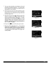
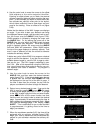
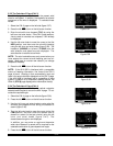
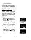
1. Select the CAL 3 page on the left side (figure 5-37).
2. Press the left C to turn on the left cursor function.
3. Enter the aircraft’s true airspeed (TAS) by using the
left inner and outer knobs. If the CAL 2 page was pre-
viously used to calculate true airspeed, it will already
be displayed.
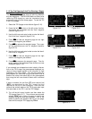
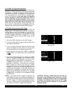
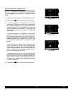
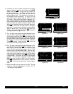
4. Use the left outer knob to move the cursor to the first
HDG position, and then enter the aircraft’s heading
using the left inner and outer knobs (figure 5-38). The
headwind (HDWND) or tailwind (TLWND) and the
wind direction and speed are now displayed. The
wind direction is relative to true North.
NOTE: The wind calculations are only correct when you
have entered the correct aircraft heading and true air-
speed. Make sure to re-enter new values if you change
airspeed or heading.
5. Press the left C to turn off the left cursor function.
NOTE: If the KLN 90B is interfaced with a compatible
source of heading information, line three of the CAL 3
page is blank. Heading is then automatically input and
used in the wind calculation displayed on the CAL 3 page.
If the KLN 90B is interfaced with a compatible air data
system in addition to a compatible heading source, the
Other 9 (OTH 9) page displays wind information directly.
5.3.4 The Calculator 4 Page (CAL 4)
The CAL 4 page is used to determine vertical navigation
descent/ascent angles to use on the NAV 4 page. To cal-
culate the required angle:
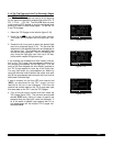
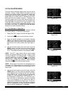
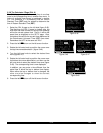
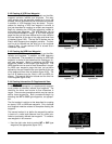
1. Select the CAL 4 page on the left side (figure 5-39).
2. Press the left C to turn on the left cursor function.
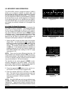
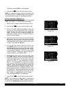
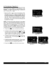
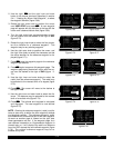
3. Use the left inner and outer knobs to enter what the
aircraft’s groundspeed will be during the descent or
ascent (figure 5-40).
4. Turn the left outer knob to move the cursor to the first
FPM position, and then enter the desired rate of
descent or ascent (in feet per minute) using the left
inner and outer knobs (figure 5-41). The
descent/ascent angle is now displayed.
In addition, you may enter an angle and determine
what rate of descent or ascent will be required for the
selected combination of groundspeed and angle.
5. Press the left C to turn off the left cursor function.
Figure 5-37
WIND |
TAS 164kt|
HDG 000^|
HDWND 12kt|
WIND 340^%|
16kt|
CAL 3
Figure 5-38
WIND |
TAS 164kt|
HDG 005^|
HDWND 11kt|
WIND 350^%|
15kt|
CRSR
Figure 5-39
VNV ANGLE |
|
GS: 175kt|
FPM: 0800|
ANGLE: 2.6^|
|
CAL 4
Figure 5-40
VNV ANGLE |
|
GS: 160kt|
FPM: 0800|
ANGLE: 2.8^|
|
CRSR
Figure 5-41
VNV ANGLE |
|
GS: 160kt|
FPM: 0500|
ANGLE: 1.8^|
|
CRSR