


3-35
Rev 1
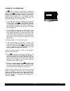
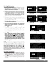
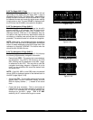
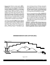
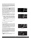
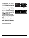
knob to display N?for North up, DTK?for desired track up
(figure 3-112), TK?for actual track up (figure 3-113), or
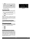
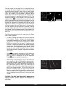
HDG?for heading up (figure 3-114). The heading up
selection is not presented as a choice if heading is not
provided to the KLN 90B. If the cursor is moved to the
map range scale using the outer knob or if the cursor is
turned off with the Cbutton, then the DTK?, TK?, or
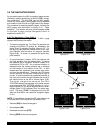
HDG?annunciation is replaced with the actual value. The
123 °displayed in the lower left corner of figure 3-115
shows how the actual track is displayed when the cursor
is not over the map orientation field as it was in figure 3-
113.
If a heading input is available to the KLN 90B then head-
ing up is usually the best map orientation to select.
Otherwise, track up display is usually preferred for use in
flight. However, the track up display is only usable when
the aircraft is moving 2 knots or more so the North up dis-
play may be a good choice while operating with very slow
ground speeds.
Notice that in both the North up format and the desired
track up format, the aircraft’s position is depicted by a dia-
mond. In the actual track up format and the heading up
format, the aircraft’s position is depicted by an aircraft
symbol.
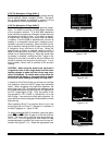
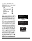
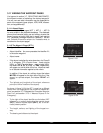
The range scale is displayed in the lower right corner of
the NAV 5 page. The range scale indicates the distance
from the aircraft’s position (the diamond or aircraft sym-
bol) to the top of the screen. Range scale selections from
1 NM to 1000 NM may be made by pressing the appropri-
ate Cand turning the appropriate inner knob. For
example, figure 3-116 illustrates the results of changing
the range scale of the map in figure 3-110 from 40 nauti-
cal miles to 15 nautical miles.
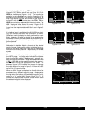
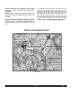
When the NAV 5 page is displayed on the left side of the
screen and any selected waypoint page is displayed on
the right side, the location of the selected waypoint is indi-
cated by a “+” on the NAV 5 page (figure 3-117). Of
course, the display scale must be chosen which allows
the selected waypoint to be displayed.
|
|
|
|
|
DTKŸ 40|
CRSR
2
3
4
i
j
Figure 3-112
|
|
|
|
|
TKŸ 40|
CRSR
2
3
4
Figure 3-113
|
|
|
|
|
HDGŸ 40|
CRSR
2
3
4
Figure 3-114
|
|
|
|
|
123^ 40|
CRSR
2
3
4
Figure 3-115
|
|
|
|
|
NŸ 15|
CRSR
3
2
i
j
Figure 3-116
| PTW D
+ |POTTSTOWN
| L
|116.50 9^W
|N 40^13.33'
NŸ 40|W 75^33.64'
NAV 5 enr-leg VOR
1
2
3
4
i
j
Figure 3-117