Page 96
Submerged Area Velocity Sensors
Section 4
Setting the Water Level
1. Take a physical measurement of the water level and enter the number
using the Level Adjust function on the instrument display.
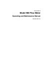
2. Measure from the surface water to the top of the pipe (B in Figure 44),
then subtract this from the pipe diameter (A in Figure 44) to get the water
level in the pipe (C in Figure 44).
3. This method prevents disturbances to the flow stream that might affect the
measurement and keeps the tape measure or ruler clean.
Figure 44 Measuring the Water Level
4.13.2 Calibrating the Submerged Area/Velocity Sensor
Calibrating the submerged area/velocity sensor synchronizes the meter
electronics with the unique characteristics of each individual probe. In
addition, the calibration compensates for a drift in the output of the sensor that
may occur as the materials in the sensor age. To ensure optimum accuracy,
the manufacturer recommends calibrating the submerged area/velocity
sensor when:
• The sensor is first used.
• Installing a new or different sensor on a flow meter or input receptacle.
• The difference between the level reading of the flow meter and the
independent verification (measurement with a dipstick and ruler) is
increasing.
Note: The data is constant if the difference between the level reading of the flow meter
and the independent verification is constant; recalibration is not required.
Note: Errors can occur with the level reading of the flow meter and the independent
verification. Errors are caused by variation in site conditions and measurement
abilities. These errors may cause slight variations in the difference, therefore, not
indicating a true change in the difference.
This calibration requires a bucket with at least 7 in. (20 cm) of water and
a ruler.
1. From the Main Menu, select
OPTIONS > ADVANCED OPTIONS >
CALIBRATION > SUBMERGED PROBE.
A
B
C