


Appendix E
Page 139
SCADA-Modbus® System Guidelines
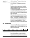
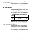
Equipment (DTE) must assert and hold high the DTR line of the DB9
connector (DSR of meter). The 980 Flow Meter does not support RTS/CTS
hardware handshaking. Note that DTE must be capable of handling a 12-
second maximum response lag.
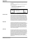
Complications with Floating Point Values
The manufacturer’s implementation of the Modbus protocol was based on the
idea that we would enable our flow meters to emulate a Modicon
®
, Compact
984 PLC. Consequently, we follow the exact same format that Modicon uses
for the storing and processing of floating point numbers. Additionally, the
Modbus protocol does not define how floating point values are packed
(stored) into the internal memory addresses or “Registers” of the flow meter. If
you are integrating our Modbus-capable flow meters, be aware that these
meters store and process floating point numbers in the exact same format as
the Modicon Compact 984 PLC.
All current models of Modicon PLCs, including the Compact 984, pack two
bytes of data into each register. This alone presents no problems. Unsigned
two-byte (16-bit) integer values in the range of 0 to 65535 can be stored and
retrieved from these registers without any problems or complications. The
complications arise when the stored value is a floating point value, which by
IEEE definition, require 4 bytes (32 bits). The IEEE standard for floating point
values states in part that the 8 most significant bits represent the exponent
and the remaining 23 bits (plus one assumed bit) represent the mantissa and
the sign of the value.
Since a data “word” consists of two bytes, a floating point value is represented
by two data words. Because a single Modicon register consists of one word
(or 2 bytes), two consecutive Modicon registers are needed to store one
floating point value.
The representation of a floating point value can be broken down into a “High
Order” and a “Low Order” word. Additionally, each word can be broken down
into a high order byte and a low order byte.
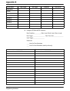
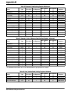
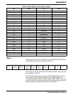
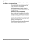
Table 40 and Table 41 depict how a IEEE floating point value is usually
represented and how the Modicon stores a floating-point value.
The complications arise because Modicon doesn't store floating point values
in this standard (IEEE) format. Modicon stores floating point values the
opposite way with the “Low-order” word in the first register and the “High-
order” word in the second register.
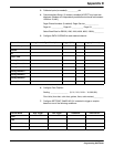
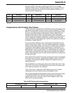
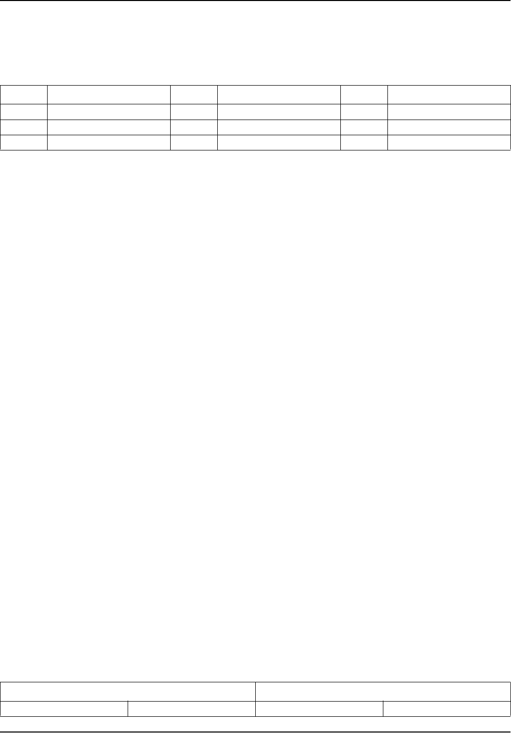
Pin Description Pin Description Pin Description
Pin 1 Data Carrier Detect (DCD)* Pin 4 Data Terminal Ready (DTR) Pin 7 Request to Send (RTS)*
Pin 2 Received Data (RD) Pin 5 Signal Ground (SG) Pin 8 Clear to Send (CTS)
Pin 3 Transmitted Data (TD) Pin 6 Data Set Ready (DSR) Pin 9 Ring Indicator*
* Not used.
Table 40 IEEE Floating Point Representation
First Register (i.e., 4001) Second Register (i.e., 4002)
High Word, High Byte High Word, Low Byte Low Word, High Byte Low Word, Low Byte