Page 92
Velocity-Only Sensor
Section 4
4.12.3 Installing the Velocity-Only Sensor in a Pipe
4.12.3.1 Important Guidelines for Velocity-Only Sensor Installation
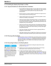
• Do not install more than one probe at a time in pipes less than 24 inches
in diameter (61 cm). Multiple probes in smaller pipes can create turbulent
or accelerated flows near the probes that may cause inaccurate
measurements.
• Mount the sensor as close as possible to the bottom of the pipe invert to
most accurately measure low velocity levels.
• Locate monitoring sites as far from inflow junctions as possible to avoid
interference caused by combined flows.
• Avoid any sites that contain flow obstacles within 2 to 4 pipe diameters in
front of the probe installation (rocks, stones, pipe joints, valve stems, etc.)
as these will contribute to turbulence and generate high speed flows in the
immediate vicinity of the obstruction.
• Avoid any sites with slow moving flows that will encourage the buildup of
silt in the invert or channel. Excessive silting around the probe may inhibit
the Doppler signal and decrease sensor accuracy, and may affect depth
measurement accuracy.
• Avoid sites with deep, rapid flows that will make it physically difficult or
dangerous to install the probe.
• Avoid sites with high velocity, low-depth flows. Splash-over and excessive
turbulence will be present around the probe and data may be inaccurate.
4.12.3.2 Choosing a Mounting Band
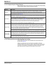
Mounting bands and rings for depth/velocity and velocity sensors are listed in
Parts and Accessories on page 157. A complete mounting band assembly for
pipe sizes less than 12 ft also requires one Depth/Velocity Sensor Mounting
Clip (Cat. No. 3263) and one Scissors Jack Assembly (for band set only)
(Cat. No. 1533).
4.12.3.3 Connecting the Sensor to the Mounting Bands
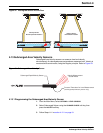
Note: If there is a large amount of
silt in the bottom of the pipe, rotate
the band until the sensor is out of
the silt (Figure 41), assuring that the
sensor remains below the minimum
expected water level at all times. Silt
should not be disturbed and must be
measured frequently if entered into
InSight
®
Gold software. A Level
Adjust is required to offset level
sensors.
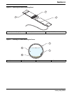
1. Attach the sensor to the sensor mounting clip using the two screws
provided. See Figure 40.
2. Attach the clip to the mounting band. Mounting Rings come with pre-
drilled holes for direct mounting of the sensor to the ring.
3. To reduce the likelihood of debris collecting on the cable and
mounting band, route the cable along the edge of the band and fasten the
cable to the mounting band with nylon wire ties. See Figure 40. The cable
should exit the tied area at, or near, the top of the pipe to keep it out of the
flow stream.


