


Section 2
Page 35
Wiring the 4–20 mA Output
The 980 Flow Meter is available with one of the following depth/velocity
measurement technologies:
After wiring the instrument and optional devices an operator must conduct the
basic programming setup (Refer to Section 3 on page 59), conduct individual
programming for the optional devices, and when necessary calibrate the
devices. (Refer to Section 4 on page 67 for operator’s setup).
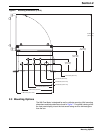
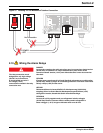
2.7 Wiring the 4–20 mA Output
Two 4–20 mA dc outputs are available and may be independently assigned to
any data channel (level, flow, pH, etc.)
The maximum cable length for either 4–20 mA output is defined based on the
load of the instrument/device being connected and the gauge of wire being
used to connect the instrument/device to the 980 Flow Meter. The total
available load for either of the 4–20 mA outputs is 600 ohms.
For example: If the device that is being connected has a load of 550 ohms,
this leaves 50 ohms available to define the maximum length of wire for
connecting the device to the 980 Flow Meter. Each wire has an inherent
resistance that can be obtained from the wire manufacturer. Divide the 50
ohms that is available for the wire by the resistance of wire (with units of
ohms/ft). The result is the maximum cable length that can be used in that
particular location. If an 18 gauge copper wire is being used, it has a
resistance of 6.39 ohms/1000 feet. Dividing 50 ohms by 6.39 ohms/1000 ft
results in a maximum cable length of 7,824 feet.
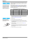
Note: To minimize electromagnetic
effects on the 980 Flow Meter,
performance shielded cable is
required. To ensure that ground
currents in inadequate ground
systems do not result in potential
shock hazards do not connect the
shields at both ends of the cable.
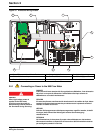
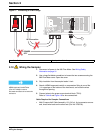
1. Disconnect all power to the 980 Flow Meter. See Wiring Safety
Information on page 31.
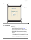
2. Use a large flat-blade screwdriver to loosen the two screws securing the
980 Flow Meter cover. Open the cover.
3. Strip insulation from 4–20 mA leads ¼ inch.
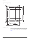
4. Attach a NEMA-approved conduit or compression fitting to one of the
½ in. openings on the bottom of the instrument, and route the 4–20 mA
cable wires through this opening.
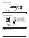
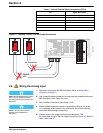
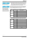
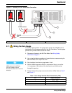
5. Connect wires to the proper screw terminal block (TB10). Refer to Ta ble 2
and Figure 13.
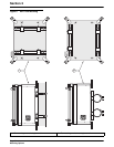
Note: Use NEMA-approved conduit
hubs (Cat. No. 16483) to ensure
that water and dust do not enter the
enclosure.
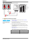
6. When wiring the cable sheild, connect to protective earth (ground) at the
980 Flow Meter. Do not connect the cable shield at the remote end of the
cable. Cut the cable jacket far enough back to expose the conductors.
Remove the shield by cutting it even with the cable jacket. Insulate the
remaining exposed shield with tape or heat-shrink tubing.
• Ultrasonic Sensor • Area Velocity/Submerged Sensor
• Velocity Sensor