


Section 2
Page 37
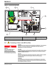
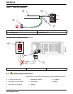
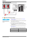
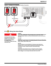
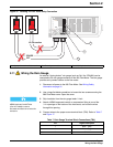
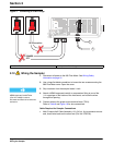
Wiring the Analog Input
Note: Input impedance for voltage
inputs is equal to 1 meg ohm.
6. When wiring the cable sheild, connect to protective earth (ground) at the
980 Flow Meter. Do not connect the cable shield at the remote end of the
cable. Cut the cable jacket far enough back to expose the conductors.
Remove the shield by cutting it even with the cable jacket. Insulate the
remaining exposed shield with tape or heat-shrink tubing.
Note: To minimize electromagnetic
affects on the 980 Flow Meter
performance, shielded cable is
required. To ensure that ground
currents in inadequate ground
systems do not result in potential
shock hazards, do not connect the
shields at both ends of the cable.
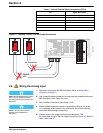
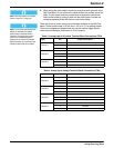
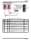
There are a total of seven analog input channels available on the 980 Flow
Meter. These inputs accept 4–20 mA dc or -4.5 to +4.5 V dc analog signals.
They can be logged and graphed and can also be used to trigger alarms,
cause set point samples, and control 4–20 mA outputs.
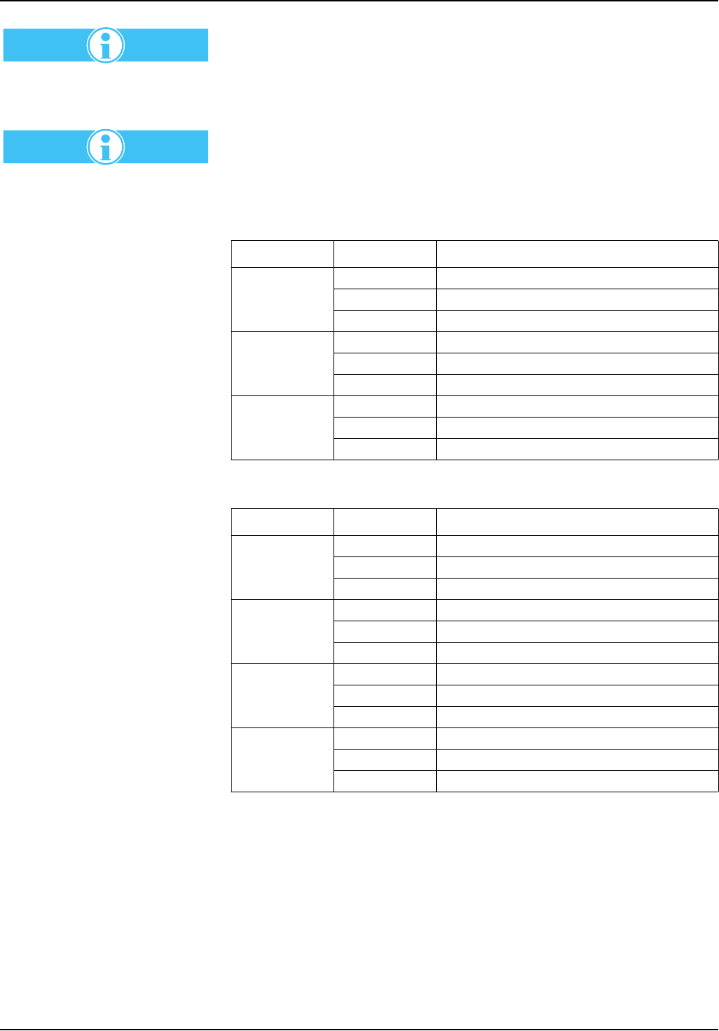
Table 3 Analog Input 4–20 mA dc Terminal Block Connections (TB4)
Input Pin Signal Description
Channel 1
4 4–20 mA dc
5 common
6shield
Channel 2
7 4–20 mA dc
8 common
9shield
Channel 3
10 4–20 mA dc
11 common
12 shield
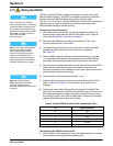
Table 4 Analog Input Voltage Terminal Block Connections (TB9)
Input Pin Signal Description
Channel 4
12 -4.5 to +4.5 V dc
11 common
10 shield
Channel 5
9 -4.5 to +4.5 V dc
8 common
7shield
Channel 6
6 -4.5 to +4.5 V dc
5 common
4shield
Channel 7
3 -4.5 to +4.5 V dc
2 common
1shield