


Page 144
SCADA-Modbus® System Guidelines
Appendix E
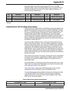
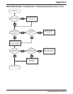
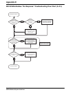
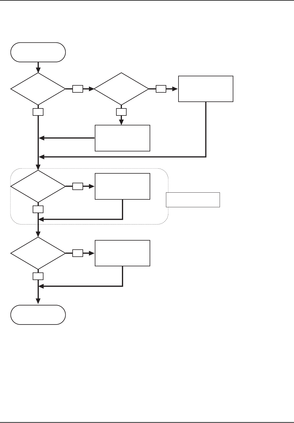
980 SCADA-Modbus “No Response” Troubleshooting Flow Chart (2 of 5)
Configure the Master device
for 7 data bits, 1 stop bit
and even parity.
Obtain a protocol converter
to convert the communication
parameters to 7 data bits,
1 stop bit, and even parity.
Configure the Master device
that is communicating with the
980 to keep the DTR (Pin C)
of the flow meter constantly
held high for the duration of all
communications.
Set the baud rate of the 980
to match that of the Modbus
Master device.
Is the
Master device
configured for 7 data bits,
1 stop bit, even
parity?
Can the
Master device be
configured for
7, 1, even?
Is there a
constant 5–18VDC
between pins C and B (GND)
of the RS-232 cable
on the 980?
Does the
baud rate of the
980 match that of the Master
device?
YES YES
YES
YES
NO NO
NO
NO
Continued from sheet 1.
Continued on sheet 3.
This section does not apply
to Modem Communication.