


Section 2
Page 43
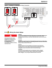
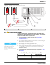
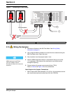
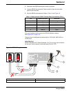
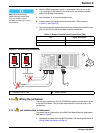
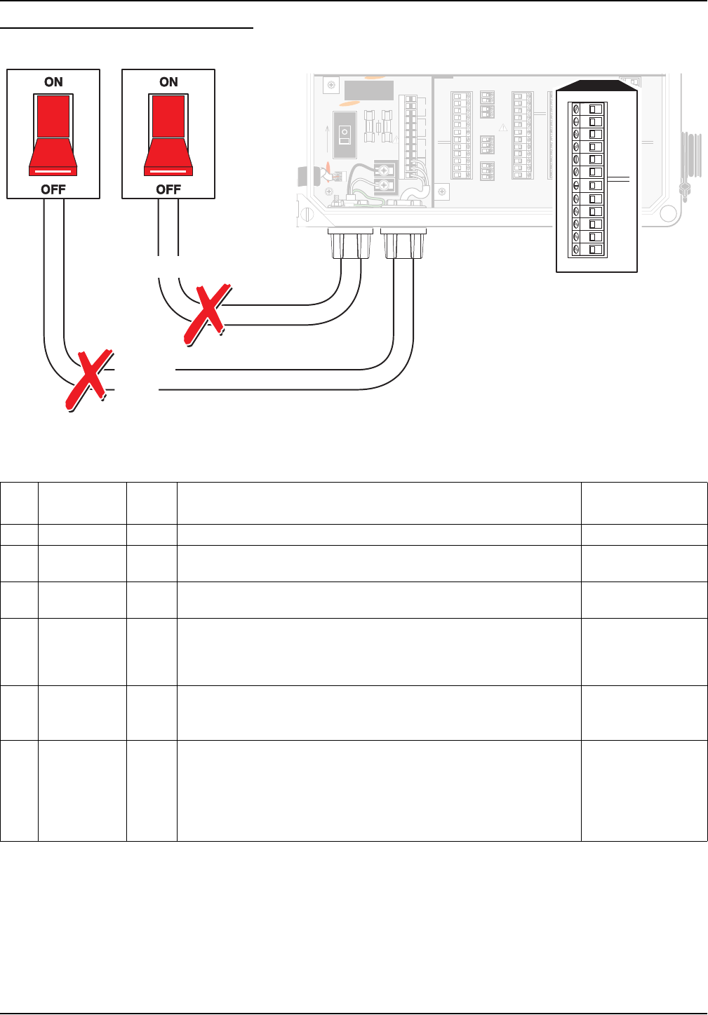
Wiring the Sampler
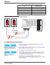
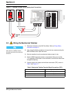
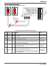
Figure 18 Locating TB10 for Sampler Connections
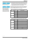
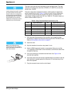
Table 8 Sampler Terminal Block Connections (TB10)
Pin
Signal
Description
Wire
Color
Purpose Rating
1 shield — Noise Suppression N/A
2 common brown
Provides the ground line used in conjunction with the other signals on
the connector.
N/A
3
flow pulse
output
yellow
Used in conjunction with common signal to notify that a pre-determined
amount of flow has accumulated.
12 to 15 V dc
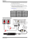
4
bottle number
input
green
Received from a wastewater sampler and used in conjunction with the
Event Input signal. It tells the flow meter which bottle was used when a
sample was taken. “Sample Times and Dates” information will appear
in the data printout when downloaded.
0 to 5 V dc input
(10 K ohm pull up
to 5 V)
5 event input red
Received from a wastewater sampler and indicates that a sample has
been collected. “Sample Taken” information will appear in the data
printout when downloaded.
0 to 5 V dc input
(11 K ohm input
resistance)
6
sampler start
output
black
Used to “wake up” a wastewater sampler when a set point condition is
met so that it can begin its sampling program. Configure the flow meter
for this pin in Set Point Sampling on page 126.
Used in conjunction with common, this line is normally allowed to float
and is switched to ground (by transistor) for the entire period that the
set point condition exists.
12 V dc (max) at
100 mA (max) open
collector output
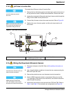
J12
J13
TB8
XMIT+
CH A+CH 4
RAIN+
1
1
1
XMIT–
RCV+
RCV–
SHEILD
AVTB11
TB10 4-20 mA
TB 9 ANALOG
TB4
RAIN
COMMON
CH A–GROUNDRAIN–
+12V
SHIELDSHIELDSHIELD
DEPTH–
CH B+CH 5CH 1
DEPTH+
CH B–GROUNDGROUND
SHIELD
SHIELDSHIELDSHIELD
COMMON
STARTCH 6CH 2
DSR
PULSEGROUNDGROUND
RXD
BOTTLESHIELDSHIELD
SHIELD
SHIELD
TOTALIZER
TB7
TB6
TB2
TB5
TOTAL –
RTD –
TIP
TIP
TOTAL +
1
1
MODEM
ULTRASONIC
RTD
RING
RING
RTD
DTR
EVENTCH 7CH 3
TXD
GROUNDGROUNDGROUND
+12V
SHIELDSHIELDSHIELD
RS232C
SAMPLERANALOGANALOG
1
1
1
1
2
2
2
2
3
3
3
3
4
4
4
4
5
5
5
5
6
6
6
6
7
7
7
7
8
8
8
8
9
9
9
9
10
10
10
10
11
11
11
11
12
12
12
12
13 14 15 16
SHIELD
TB3
pH
REF
pH
RTD
–5V
GROUND
+5V
485A
485B
485+NO
NO
NO
NO
485GNDCOM RELAY 1
COM RELAY 2
COM RELAY 3
COM RELAY 4
SHIELDNC
NC
NC
NC
RS485
1 2 3 4 5 6 7 8 9 10 11 12
F2
F1
HOT/ 1
NEU/ 2
T, 1.0A 250V
ON
HOT/ 1
NEU/ 2
TB8
1
4
7
10
2
5
8
11
3
6
9
12
J13
J12
J13
TB8
XMIT+
CH A+CH 4
RAIN+
1
1
1
XMIT–
RCV+
RCV–
SHEILD
AVTB11
TB10 4-20 mA
TB 9 ANALOG
TB4
RAIN
COMMON
CH A–GROUNDRAIN–
+12V
SHIELDSHIELDSHIELD
DEPTH–
CH B+CH 5CH 1
DEPTH+
CH B–GROUNDGROUND
SHIELD
SHIELDSHIELDSHIELD
COMMON
STARTCH 6CH 2
DSR
PULSEGROUNDGROUND
RXD
BOTTLESHIELDSHIELD
SHIELD
SHIELD
TOTALIZER
TB7
TB6
TB2
TB5
TOTAL –
RTD –
TIP
TIP
TOTAL +
1
1
MODEM
ULTRASONIC
RTD
RING
RING
RTD
DTR
EVENTCH 7CH 3
TXD
GROUNDGROUNDGROUND
+12V
SHIELDSHIELDSHIELD
RS232C
SAMPLERANALOGANALOG
1
1
1
1
2
2
2
2
3
3
3
3
4
4
4
4
5
5
5
5
6
6
6
6
7
7
7
7
8
8
8
8
9
9
9
9
10
10
10
10
11
11
11
11
12
12
12
12
13 14 15 16
SHIELD
TB3
pH
REF
pH
RTD
–5V
GROUND
+5V
485A
485B
485+NO
NO
NO
NO
485GNDCOM RELAY 1
COM RELAY 2
COM RELAY 3
COM RELAY 4
SHIELDNC
NC
NC
NC
RS485
1 2 3 4 5 6 7 8 9 10 11 12
F2
F1
HOT/ 1
NEU/ 2
T, 1.0A 250V
ON
HOT/ 1
NEU/ 2
TB8
1
4
7
10
2
5
8
11
3
6
9
12
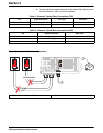
J13
CH A+
TB10 4-20 mA
CH A–
SHIELD
CH B+
CH B–
SHIELD
START
EVENT
BOTTLE
PULSE
GROUND
SHIELD
SAMPLER
123456789101112
POWER
OFF
No Connection