Page 40
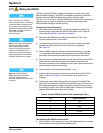
Wiring the Alarm Relays
Section 2
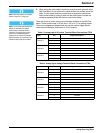
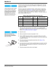
Note: Current to the relay contacts
must be limited to 5 amps. A means
to remove power from the relays
locally in case of an emergency or
for servicing the product must be
provided by the user. This can be
accomplished with an external
switch and a 5-amp fuse or with a
switched 5-amp circuit breaker.
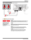
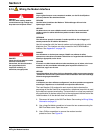
The alarm wiring can be sized according to the load being used. The relay
connector will accept wire sizes from 18 AWG to 12 AWG. Do not use wire
smaller than 18 AWG.
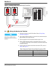
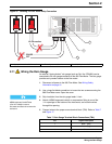
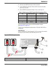
The alarm relays have unpowered contacts, and the power to operate the
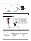
load is supplied by the user. Figure 16 shows a typical wiring configuration.
The wires are routed through the conduit hole and are connected to the
circuit board. Voltage range is 30–230 V ac, 50/60 Hz. The alarm relays can
switch resistive loads of up to 5 A.
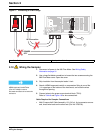
1. With the power disconnected to the controller, use a large flat-blade
screwdriver to loosen the two screws securing the 980 Flow Meter cover.
Refer to Wiring Safety Information on page 31.
Note: Use NEMA-approved
conduit hubs (Cat. No. 16483) to
ensure that water and dust do not
enter the enclosure.
2. Open the cover.
3. Strip the insulation from alarm relay leads ¼ inch.
4. Attach a NEMA-approved conduit or compression fitting to one of the
½ in. openings on the bottom of the instrument, and route the cable wires
through this opening.
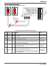
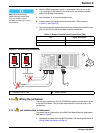
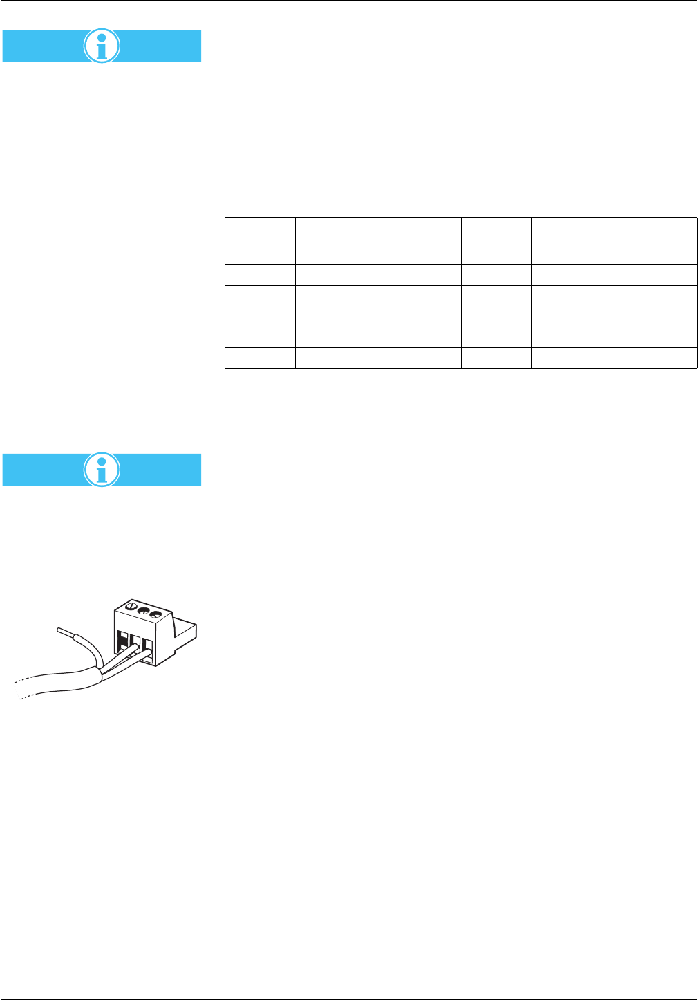
5. Pull out the twelve-pin removable terminal block. See Figure 16 for
terminal block position.
6. Insert each bare wire end into the supplied twelve-pin connector until the
wire insulation is seated against the connector. Do not leave any of the
bare wire exposed.
7. Plug the connector back onto the circuit board.
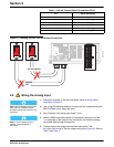
Table 6 Relay Terminal Block Connections (J13)
J13 Signal Description J13 Signal Description
1 normally closed 1 7 normally closed 3
2 common relay 1 8 common relay 3
3 normally open 1 9 normally open 3
4 normally closed 2 10 normally closed 4
5 common relay 2 11 common relay 4
6 normally open 2 12 normally open 4
3
2
1


